 Kia Rio: Shift Lever Removal
| Shift Lever Assembly Replacement |
| 1. |
Remove the floor Interior console assembly.
(Refer to "Interior (Console)" in BD group)
|
| 2. |
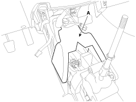
Remove the heater duct (A).
|
| 3. |
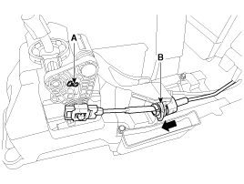
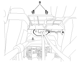
Remove the select cable assembly after removing select cable snap
pin (A) and clip (B).
|
| 4. |
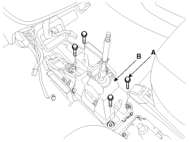
Remove the shift lever assembly (B) by removing the bolts (A-4ea).
|
| 5. |
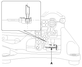
Remove the shift lever assembly (B) by removing the clip (A).
|
| Select / Shift Cable Replacement |
| 1. |
Remove the floor Interior console assembly.
(Refer to "Interior (Console)" in BD group)
|
| 2. |
Remove the heater duct (A).
|
| 3. |
Remove the select cable assembly after removing select cable snap
pin (A) and clip (B).
|
| 4. |
Remove the shift lever assembly (B) by removing the bolts (A-4ea).
|
| 5. |
Remove the clip (A) from the shift cable assembly.
|
| 6. |
Remove the crash pad.
(Refer to "Interior (Crash pad)" in BD group.)
|
| 7. |
Remove the heater unit.
(Refer to "Heater (Heater unit)" in HA group.)
|
| 8. |
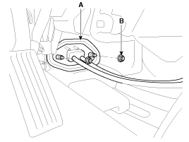
Remove the retainer (A) and nuts (B-2ea).
|
| 9. |
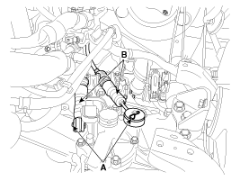
Remove the pins (A).
|
| 10. |
Remove the cable (B) from the cable bracket at manual transaxle
assembly side.
|
| 11. |
Remove the shift cable and select cable at cabin room.
|
| 12. |
Installation is the reverse of removal.
|
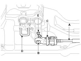
[Shift / Select Cable Installation Tips]
| 1. |
Installation the select and shift cable assembly (B) after removing
the pin (A).
|
| 2. |
Installation is the shift cable (A).
|
| 3. |
Installation is the shift lever assembly (A).
|
| 4. |
Shift to the 3th gear position.
|
| 5. |
Insert the selected cable (A) to the shift lever assembly pin
(B).
|
| 6. |
You have to push in the adjuster (C).
|
| 7. |
Remove the neutral position pin (D).
|
| 8. |
Install the snap pin (E).
|
 Shift Lever Components
1. Shift lever knob
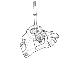
2. Shift lever assembly
3. Select cable assembly
4. Shift cable assembly
5. Retainer
...
 Shift Lever Inspection
1.
Check the select cable for proper operation and for damage.
2.
Check the shift cable for proper operation and for damage.
...
See also:
Installation
Installation is in the reverse order of removal.
Perform the following :
Х
Adjust a shift cable.
Х
Refill engine with engine oil.
...
Control System Composition
Fault Diagnosis
Features a fail-safe mechanism that prevents dangerous situations from
developing in the event of a transaxle failure. The limp home mode engages if
the transaxle malf ...
Copyright © www.kirmanual.com 2014-2024

