 Kia Rio: Power Door Lock Actuators Inspection
Front Door Lock Actuator and Switch
| 1. |
Remove the front door trim.
(Refer to the Body group - Front door)
|
| 2. |
Remove the front door latch.
(Refer to the Body group - Front door).
|
| 3. |
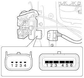
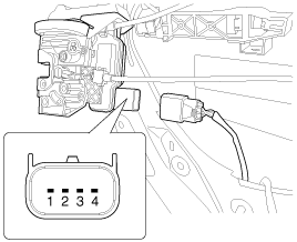
Disconnect the connectors from the actuator.
|
| 4. |
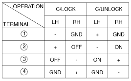
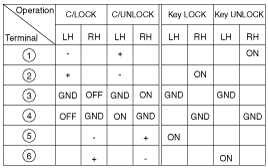
Check actuator operation by connecting power and ground according
to the table.
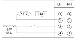
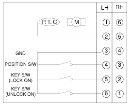
Check for continuity between the terminals in each switch position
when inserting the key into the door according to the table
[Without key (4Pin)]
[With key (6Pin)]
|
Rear Door Lock Actuator and Switch
| 1. |
Remove the rear door trim.
(Refer to the Body group - Rear door)
|
| 2. |
Remove the rear door latch.
(Refer to the Body group - Rear door)
|
| 3. |
Disconnect the connectors from the actuator.
|
| 4. |
Check actuator operation by connecting power and ground according
to the table.
Check for continuity between the terminals in each switch position
when inserting the key into the door according to the table
|
 Component Location
1. Driver power window switch
2. Door lock switch
3. BCM (Body Control Module)
4. Front door lock actuator
5. Rear door lock actuator
6. Internal junction box
...
 Power Door Lock Switch Inspection
Driver Door Lock Switch Inspection
1.
Disconnect the negative (-) battery terminal.
2.
Remove the front door trim panel.
(Refer to t ...
See also:
If you have a flat tire (Tire mobility kit, if equipped)
For safe operation, carefully read and follow the instructions in this manual
before use.
(1) Compressor
(2) Sealant bottle
The Tire Mobility Kit is a temporary fix to the tire and the tire sho ...
Water pump: Inspection
1.
Check each part for cracks, damage or wear, and replace the coolant
pump assembly if necessary.
2.
Check the bearing for damage, abnorma ...
Component Location (1)
1. Head lamp (Low/ High)
2. Head lamp (Low)
3. Head lamp (High)
4. Turn signal lamp
5. DRL/ Position lamp
6. Side marker lamp
7. Turn signal lamp (Door mirror)
8. F ...
Copyright ® www.kirmanual.com 2014-2026

