
 Kia Rio: Schematic Diagrams
Circuit Diagram - ESC (1)
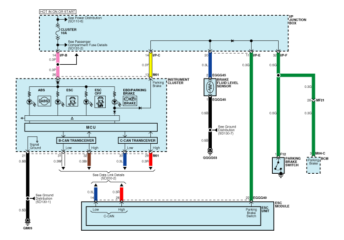
Circuit Diagram - ESC (2)
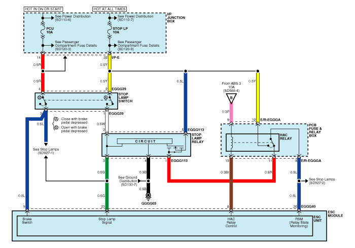
Circuit Diagram - ESC (3)
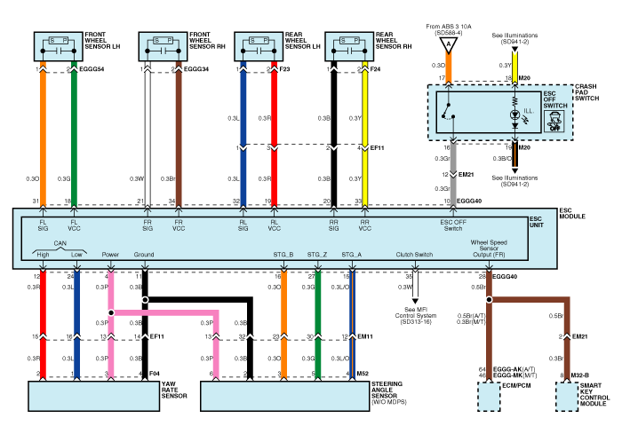
Circuit Diagram - ESC (4)
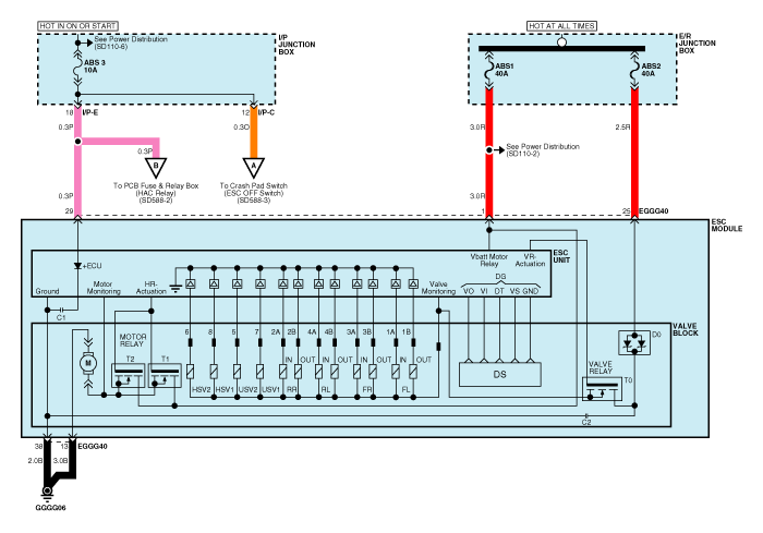
ESC connector input/output
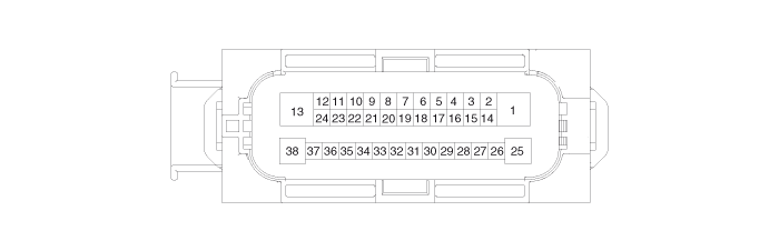
| Connector Terminal |
Specification |
Remark |
|
| No |
Description |
||
| 29 |
IGNITION1(+) |
High level of wake up voltage : 4.5V < V < 16.0V Low level of wake up voltage : V < 2.4V Max. current : I < 50mA |
|
| 25 |
POS. BATTERY 1.(SOLENOID) |
Over voltage range : 17.0 ± 0.5V Operating voltage range : 10.0 ± 0.5V < V < 16.0 ± 0.5V Low voltage range : 7.0 ± 0.5V < V < 9.5 ± 0.5V Max. current : I < 40A Max. leakage current : I < 0.25mA |
|
| 1 |
POS. BATTERY 2.(MOTOR) |
Operating voltage range: 10.0 ± 0.5V < V < 16.0 ± 0.5V Rush current : I < 110A Max current : I < 40A Max leakage current : I < 0.25mA |
|
| 38 |
GROUND |
Rated current : I <550mA Max. current: I < 40A |
|
| 13 |
PUMP MOTOR GROUND |
Rush current : I < 110A Max current : I < 40A |
|
| 11 |
SENSOR GROUND |
Rated current : I <250mA |
|
| 4 |
SENSOR POWER |
Max current Capability : I < 250mA Max voltage : V_BAT1 -0.8V |
|
| 23 |
BRAKE LIGHT SWITCH |
Input voltage (Low) : V < 2.0V Input voltage (High) : V > 6.0V Max. Input current : I < 3mA (@12.8V) |
|
| 10 |
ESC ON/OFF SWITCH |
||
| 9 |
BRAKE SWITCH |
||
| 22 |
PARKING BRAKE SWITCH |
Input voltage (Low) : V < 2.0V Input voltage (High) : V > 6.0V Max input current : I < 5mA (@12.8V) |
|
| 35 |
CLUTCH SWITCH |
||
| 28 |
SENSOR FRONT RIGHT OUTPUT |
External pull up resistance :1 KΩ < R Output duty : 50 ± 20% |
|
| 14 |
CAN BUS LINE(LOW) |
Max. Input current : I < 10mA |
|
| 26 |
CAN BUS LINE(HIGH) |
||
| 18 |
SENSOR FRONT LEFT POWER |
Output voltage : V_BAT1 -0.6V ~ V_BAT1 -1.1V Output current : Max 30mA |
|
| 34 |
SENSOR FRONT RIGHT POWER |
||
| 19 |
SENSOR REAR LEFT POWER |
||
| 33 |
SENSOR REAR RIGHT POWER |
||
| 31 |
SENSOR FRONT LEFT SIGNAL |
Input current LOW : 5.9 ~ 8.4mA Input current HIGH : 11.8 ~ 16.8mA Frequency range : 1 ~ 2,500Hz Input duty : 50 ± 10% |
|
| 21 |
SENSOR FRONT RIGHT SIGNAL |
||
| 32 |
SENSOR REAR LEFT SIGNAL |
||
| 20 |
SENSOR REAR RIGHT SIGNAL |
||
| 12 |
CAN SENSOR LINE (HIGH) |
Max. input current : I < 10mA |
|
| 24 |
CAN SENSOR LINE (LOW) |
||
| 8 |
HAC RELAY DRIVE |
Max. current : I < 180mA Max output voltage : V< 1.2V |
|
| 36 |
HAC RELAY STATE MONITORING |
Input voltage (Low) : V < 2V Input voltage (High) : V > 6V Max input current : I < 10mA (@12.8V) |
|
| 11 |
STEERING ANGLE SENSOR PHASE A |
Input duty (STG A, STG B) : 50 ± 10% Phase Difference (STG A, STG B) : 2 ± 0.6 deg High voltage : 3.0V < V_H < 4.1V Low voltage : 1.3V < V_L < 2.0V |
without MDPS |
| 1 |
STEERING ANGLE SENSOR PHASE B |
||
| 27 |
STEERING ANGLE SENSOR PHASE Z |
||
 ESC Operation Mode
ESC Hydraulic System Diagram
1.
ESC Non-operation : Normal braking.
Solenoid valve
Continuity
Valve
Motor ...
 Failure Diagnosis
1.
In principle, ESC and TCS controls are prohibited in case of ABS
failure.
2.
When ESC or TCS fails, only the failed system control is pr ...
See also:
Windshield Glass Components
1. Windshield glass
2. Windshield glass moulding
...
Fuel requirements
Your new Kia vehicle is designed to use only unleaded fuel having a pump octane
number ((R+M)/2) of 87 (Research Octane Number 91) or higher.
Your new vehicle is designed to obtain maximum performa ...
Weight Classification System (WCS) Description
WCS is intended to detect the occupant’s physique in order to determine
whether the passenger airbag should be suppressed or deployed. WCS classifies
the front passenger side seat by measur ...
