 Kia Rio: Starter: Disassembly
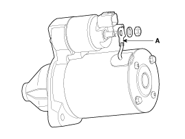
| 1. |
Disconnect the M-terminal (A) on the magnet switchassembly.
|
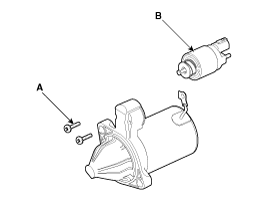
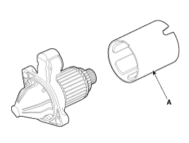
| 2. |
After loosening the 2 screws (A), detach the magnetswitch assembly
(B).
|
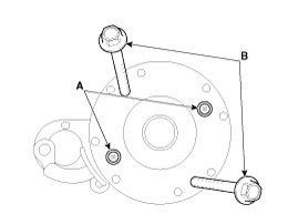
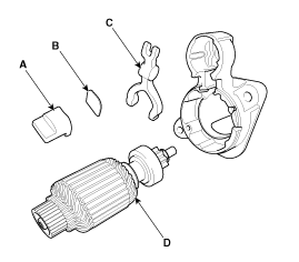
| 3. |
Loosen the brush holder mounting screw (A) and the trough bolts
(B).
|
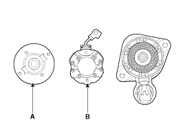
| 4. |
Remove the rear bracket (A) and brush holderassembly (B).
|
| 5. |
Remove the yoke (A).
|
| 6. |
Remove the packing (A), lever plate (B), lever (C), armature (D).
|
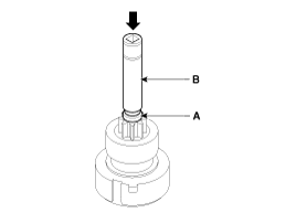
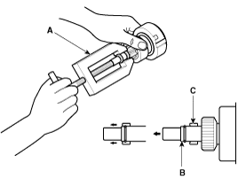
| 7. |
Press the stopper (A) using a socket (B).
|
| 8. |
After removing the stop ring (A) using stopper pliers (B).
|
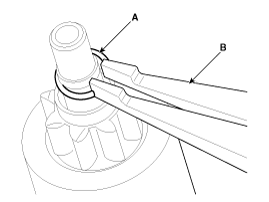
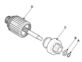
| 9. |
Remove the stop ring (B), stopper (A), overrunningclutch (C) and
armature (D).
|

 Starter: Installation
1.
Install in the reverse order of removal.
Starter installation bolt:
49.0 ~ 63.7 N.m (5.0 ~ 6.5 kgf.m, 36.2 ~ 47.0 lb-ft)
...
 Starter: Reassembly
1.
Reassemble in the reverse order of disassembly.
...
See also:
Smart key unit Inspection
Smart Key Unit
-
Refer to the BE group - inspection / self diagnosis with GDS.
Smart Key Switch
-
Refer to the BE group - inspection / self di ...
Removal
1.
Turn the ignition switch OFF and disconnect the battery negative
(-) cable.
2.
Disconnect the crankshaft position sensor connector (A) ...
Transaxle Control Module (TCM) Installation
1.
Installation is reverse of removal.
In the case of the vehicle equipp ...
Copyright © www.kirmanual.com 2014-2024