 Kia Rio: Removal
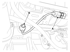
| 1. |
Turn the ignition switch OFF and disconnect the battery negative
(-) cable.
|
| 2. |
Remove the intake manifold (Refer to “Intake And Exhaust System”
in EM group).
|
| 3. |
Disconnect the injector connector (A).
|
| 4. |
Remove the installation bolt (B), and then remove the sensor from
the cylinder block.
|
 Circuit Diagram
(M/T)
(A/T)
...
 Installation
•
Install the component with the specified torques.
•
...
See also:
Compressor Inspection
1.
Check the plated parts of the disc & hub assembly (A) for color
changes, peeling or other damage. If there is damage, replace the clutch
set.
...
Circuit Diagram
(M/T)
(A/T)
...
Smart key unit Circuit diagram
No.
Connector A(26 pins)
No.
Connector B(16 pins)
No.
Connector C(22 pins)
1
VBAT_LOAD
1
C_CAN_L
1
O_S ...
Copyright © www.kirmanual.com 2014-2024