 Kia Rio: Removal
| 1. |
Remove the following items;
|
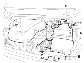
| 2. |
Remove the ground line after removing the bolt (A).
|
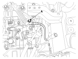
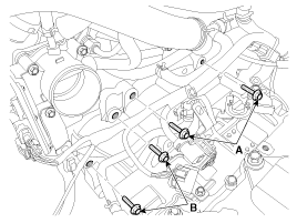
| 3. |
Dissconnect the solenoid valve connector (A) and inhibitor switch
connector (B).
|
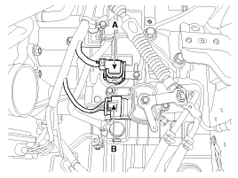
| 4. |
Remove the control cable (C) after removing the nut (A) and the
bolt (B).
|
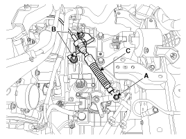
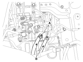
| 5. |
Disconnect the hose (B) after removing the automatic transaxle
fluid cooler hose clamp (A).
|
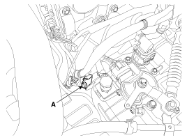
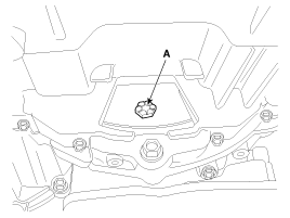
| 6. |
Remove the wiring mounting bolt (A).
|
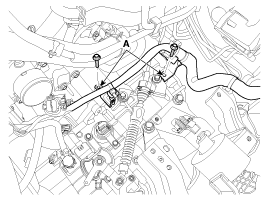
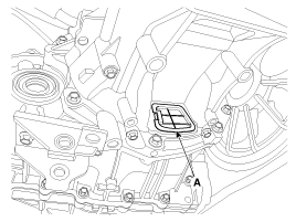
| 7. |
Remove the solenoid valve connector and inhibitor switch connector
wiring mounting bracket (A).
|
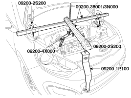
| 8. |
Using the engine support fixture (Support SST No.: 09200-2S200,
Adapter SST No.: 09200-1P000, 4X000, Beam SST No.: 09200-38001/3N000),
hold the engine and transaxle assembly safely.
|
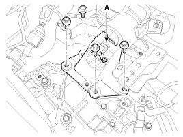
| 9. |
Remove the automatic transaxle upper mounting bolt (A-2ea) and
the starter motor mounting bolt (B-2ea).
|
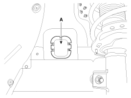
| 10. |
Remove the mounting cover (A).
|
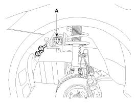
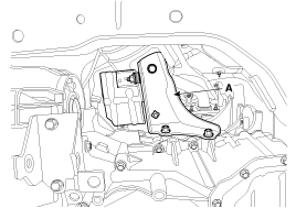
| 11. |
Remove the support bracket mounting bolts (A).
|
| 12. |
Remove the automatic transaxle support bracket (A).
|
| 13. |
Lift the vehicle with a jack.
|
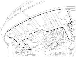
| 14. |
Remove the under cover (A).
|
| 15. |
Remove the drive shaft assembly.
(Refer to "Drive shaft assembly" in DS group.)
|
| 16. |
Remove the drive shaft cover (A).
|
| 17. |
Remove the dust cover (A).
|
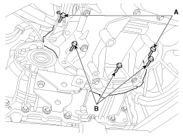
| 18. |
Remove the torque converter mounting bolt (A-4ea) with rotating
the crankshaft.
|
| 19. |
Remove the roll rod bracket (C) after removing bolt (A,B).
|
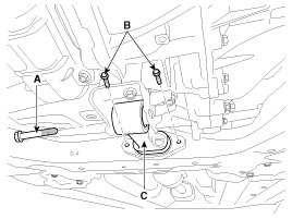
| 20. |
Remove the automatic transaxle with a jack after removing the
mounting bolt (A-2ea, B-3ea).
|
 Components Location
1. Converter housing
2. Shift cable bracket
3. Automatic transaxle case
4. Rear cover
5. Valve body cover
6. Manual control lever
7. Air breather hose
8. Inhibi ...
 Installation
1.
Installation is the reverse of removal.
If the oil seal on the transaxle case side is da ...
See also:
Side Airbag (SAB) Module Components
...
Description
The SMART KEY system is a system that allows the user to access and operate
a vehicle in a very convenient way. To access the vehicle, no traditional key
or remote control unit is needed.
...
Rear Wheel Speed Sensor Inspection
1.
Measure the output voltage between the terminal of the wheel speed
sensor and the body ground.
...
Copyright © www.kirmanual.com 2014-2024