 Kia Rio: Shift Lever Removal
| Shift Lever Assembly Replacement |
| 1. |
Remove the center console.
(Refer to "interior (console)" in BD group)
|
| 2. |
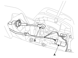
Disconnect the connector (A)
|
| 3. |
Remove the control cable (B).
|
| 4. |
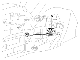
Remove the shift lock cable (A).
|
| 5. |
Remove the wiring clip (A).
|
| 6. |
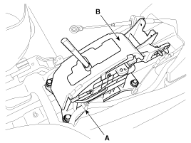
Remove the AT lever(shift lever) assembly (B) by removing the
bolts (4ea).
|
| 7. |
Installation is the reverse of removal.
Adjust the shift lock cable.
(Refer to "adjustment shift lock cable" in this group)
|
| Control Cable Assembly Replacement |
| 1. |
Remove the center console.
(Refer to "interior (console)" in BD group)
|
| 2. |
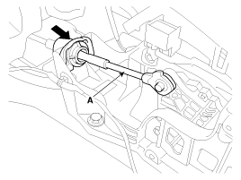
Remove the control cable (A).
|
| 3. |
Remove the crash pad.
(Refer to "Interior(Crash pad)" in BD group.)
|
| 4. |
Remove the heater unit.
(Refer to "Heater(Heater unit)" in HA group.)
|
| 5. |
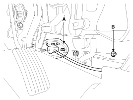
Remove the retainer (A) and nuts (B).
|
| 6. |
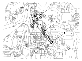
Remove the nut (A) from the manual control lever.
|
| 7. |
Remove the control cable (B) from the bracket (C) at transaxle
assembly side.
(Refer to "Automatic Transaxle" in this group)
|
| 8. |
Remove the control cable at cabin room.
|
| 9. |
Installation is the reverse of removal.
|
| Shift Lock Cable Replacement |
| 1. |
Remove the center console.
(Refer to "interior(console)"in BD group.
|
| 2. |
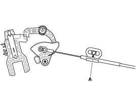
Remove the shift lock cable (A).
|
| 3. |
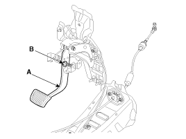
Remove the shift lock cable (B) from the brake pedal (A).
|
| 4. |
Installation is the reverse of removal.
|
 Shift Lever Components
1. Shift lever knob
2. Shift lever assembly
3. Control cable
4. Shift lock cable assembly
5. Retainer
6. Brake pedal assembly
...
 Shift Lever Adjustment
Adjusting the control cable
1.
Set room side AT lever(shift lever) and automatic transaxle side
manual control lever to "N" position.
...
See also:
Front Impact Sensor (FIS) Description
The front impact sensor (FIS) is installed in the front side member. They
are remote sensors that detect acceleration due to a collision at its mounting
location. The primary purpose of the F ...
35R Clutch Control Solenoid Valve(35R/C_VFS) Circuit Diagram
...
Trunk Lid Adjustment
1.
After loosening the trunk lid hinge (A) mounting bolt, adjust
the trunk lid by moving it up or down, or right or left.
2.
Adjust the tru ...
Copyright © www.kirmanual.com 2014-2024

