 Kia Rio: Cluster Ionizer (FATC only) Replacement
| 1. |
Disconnect the negative (-) battery terminal.
|
| 2. |
Remove the glove box.
(Refer to BD group - "Crash Pad")
|
| 3. |
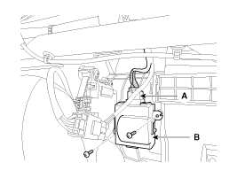
Disconnect the connector (A) and then remove the cluster ionizer
(B) after loosening the mounting screws.
|
| 4. |
Install in the reverse order of removal.
|
 Cluster Ionizer (FATC only) Inspection
1.
Press the MODE switch more then 4 times within 2 seconds while
pressing the OFF switch.
Display
Fail description
00 ...
 Heater
...
See also:
Installation
1.
Remove the ignition key from the vehicle.
2.
Disconnect the battery negative cable and wait for at least thirty
seconds.
...
Transaxle Control Module (TCM) Installation
1.
Installation is reverse of removal.
In the case of the vehicle equipp ...
Specifications
Fuel Delivery System
Items
Specification
Fuel Tank
Capacity
43 lit. (11.4 U.S.gal., 45.4 U.S.qt., 37.8 Imp.qt.)
Fuel Filter
...
Copyright ® www.kirmanual.com 2014-2025

