 Kia Rio: Crash Pad Replacement
Cluster Replacement
| ŌĆó
|
A plastic trim tool is recommended, but if prying with
a screwdriver, wrap it with protective tape, and apply protective
tape around the related parts, to prevent damage.
|
| ŌĆó
|
Take care not to bend or scratch the trim and panels.
|
| ŌĆó
|
Put on gloves to protect your hands.
|
|
|
1. |
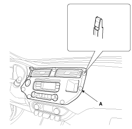
Using a screwdriver or remover, remove the center fascia panel
(A).
|
|
2. |
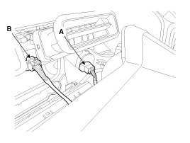
Disconnect the start/stop button connector (A) and hazard switch
connector (B).
|
|
3. |
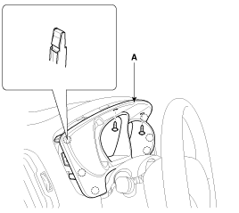
Using a screwdriver or remover, remove the cluster fascia panel
(A).
|
|
4. |
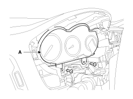
After loosening the mounting screws, then remove the cluster assembly
(A).
|
|
5. |
Disconnect the cluster connector (A).
|
|
6. |
Installation is the reverse of removal.
|
ŌĆó |
Make sure the connectors are connected in properly.
|
|
ŌĆó |
Replace any damage clips.
|
|
|
Center Fascia Panel Replacement
| ŌĆó
|
A plastic trim tool is recommended, but if prying with
a screwdriver, wrap it with protective tape, and apply protective
tape around the related parts, to prevent damage.
|
| ŌĆó
|
Take care not to bend or scratch the trim and panels.
|
| ŌĆó
|
Put on gloves to protect your hands.
|
|
|
1. |
Using a screwdriver or remover, remove the center fascia panel
(A).
|
|
2. |
Disconnect the start/stop button connector (A) and hazard switch
connector (B).
|
|
3. |
Installation is the reverse of removal.
|
ŌĆó |
Make sure the connector are connected in properly.
|
|
ŌĆó |
Replace any damage clips.
|
|
|
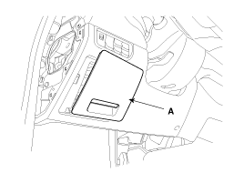
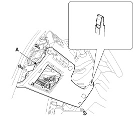
Crash Pad Lower Panel Replacement
| ŌĆó
|
A plastic trim tool is recommended, but if prying with
a screwdriver, wrap it with protective tape, and apply protective
tape around the related parts, to prevent damage.
|
| ŌĆó
|
Take care not to bend or scratch the trim and panels.
|
| ŌĆó
|
Put on gloves to protect your hands.
|
|
|
1. |
Using a screwdriver or remover, remove the crash pad side cover
(A).
|
|
2. |
Using a screwdriver or remover, remove the fuse box cover (A).
|
|
3. |
After loosening the mounting screws and bolt, then remove the
crash pad lower panel (A).
|
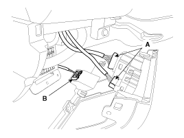
|
4. |
Disconnect the connectors (A) and diagnosis connector (B).
|
|
5. |
Installation is the reverse of removal.
|
ŌĆó |
Make sure the connectors are connected in properly.
|
|
ŌĆó |
Replace any damage clips.
|
|
|
Audio assembly Replacement
| ŌĆó
|
A plastic trim tool is recommended, but if prying with
a screwdriver, wrap it with protective tape, and apply protective
tape around the related parts, to prevent damage.
|
| ŌĆó
|
Take care not to bend or scratch the trim and panels.
|
| ŌĆó
|
Put on gloves to protect your hands.
|
|
|
1. |
Using a screwdriver or remover, remove the center fascia panel
(A).
|
|
2. |
Disconnect the start/stop button connector (A) and hazard switch
connector (B).
|
|
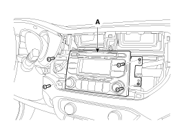
3. |
After loosening the mounting screws, then remove the audio assembly
(A).
|
|
4. |
Disconnect the connectors (A).
|
|
5. |
Installation is the reverse of removal.
|
ŌĆó |
Make sure the connectors are connected in properly.
|
|
ŌĆó |
Replace any damaged clips.
|
|
|
Heater Control Unit Replacement
| ŌĆó
|
A plastic trim tool is recommended, but if prying with
a screwdriver, wrap it with protective tape, and apply protective
tape around the related parts, to prevent damage.
|
| ŌĆó
|
Take care not to bend or scratch the trim and panels.
|
| ŌĆó
|
Put on gloves to protect your hands.
|
|
|
1. |
Using a screwdriver or remover, remove the heater control unit
(A).
|
|
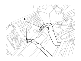
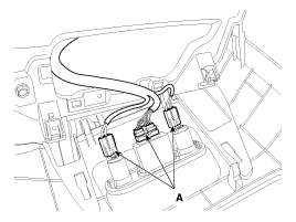
2. |
Disconnect the connectors (A) and hose (B).
|
|
3. |
Installation is the reverse of removal.
|
ŌĆó |
Make sure the connectors are connected in properly.
|
|
ŌĆó |
Replace any damaged clips.
|
|
|
Glove Box Replacement
| ŌĆó
|
A plastic trim tool is recommended, but if prying with
a screwdriver, wrap it with protective tape, and apply protective
tape around the related parts, to prevent damage.
|
| ŌĆó
|
Take care not to bend or scratch the trim and panels.
|
| ŌĆó
|
Put on gloves to protect your hands.
|
|
|
1. |
Using a screwdriver or remover, remove the crash pad side cover
(A).
|
|
2. |
Disconnect the pins (A) and then remove the glove box (B).
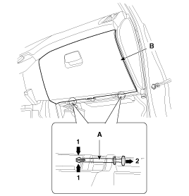
|
|
3. |
After loosening the mounting screws, then remove the glove box
housing (A).
|
|
4. |
Disconnect the glove box lamp connector (A).
|
|
5. |
Installation is the reverse of removal.
|
ŌĆó |
Make sure the connectors are connected in properly.
|
|
ŌĆó |
Replace any damage clips.
|
|
|
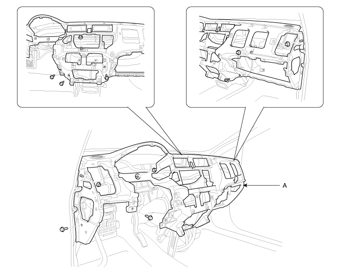
Crash Pad Center Panel Replacement
| ŌĆó
|
A plastic trim tool is recommended, but if prying with
a screwdriver, wrap it with protective tape, and apply protective
tape around the related parts, to prevent damage.
|
| ŌĆó
|
Take care not to bend or scratch the trim and panels.
|
| ŌĆó
|
Put on gloves to protect your hands.
|
|
|
1. |
Remove the following items :
| A. |
Floor console assembly
(Refer to the BD group ŌĆō ŌĆ£ConsoleŌĆØ)
|
| B. |
Crash pad side cover [LH, RH]
|
| D. |
Glove box & Glove box housing
|
|
|
2. |
Using a screwdriver or remover, remove the crash pad center panel
(A).
|
|
3. |
Disconnect the connectors (A).
|
|
4. |
Installation is the reverse of removal.
|
ŌĆó |
Make sure the connectors are connected in properly.
|
|
ŌĆó |
Replace any damage clips.
|
|
|
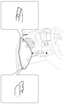
Steering Column Lower Shroud Assembly Replacement
| ŌĆó
|
A plastic trim tool is recommended, but if prying with
a screwdriver, wrap it with protective tape, and apply protective
tape around the related parts, to prevent damage.
|
| ŌĆó
|
Take care not to bend or scratch the trim and panels.
|
| ŌĆó
|
Put on gloves to protect your hands.
|
|
|
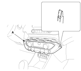
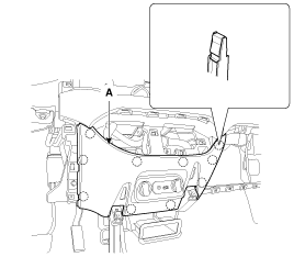
1. |
After loosening the mounting screws, then remove the steering
column lower shroud assembly (A).
|
|
2. |
Installation is the reverse of removal.
|
ŌĆó |
Replace any damage clips.
|
|
|
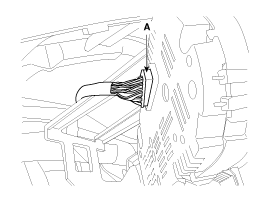
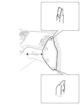
Crash Pad Side Cover Replacement
| ŌĆó
|
A plastic trim tool is recommended, but if prying with
a screwdriver, wrap it with protective tape, and apply protective
tape around the related parts, to prevent damage.
|
| ŌĆó
|
Take care not to bend or scratch the trim and panels.
|
| ŌĆó
|
Put on gloves to protect your hands.
|
|
|
1. |
Using a screwdriver or remover, remove the crash pad side cover
(A).
[Driver's]
[Passenger's]
|
|
2. |
Installation is the reverse of removal.
|
ŌĆó |
Replace any damaged clips.
|
|
|
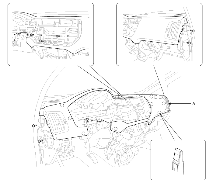
Crash Pad Upper Panel Replacement
| ŌĆó
|
A plastic trim tool is recommended, but if prying with
a screwdriver, wrap it with protective tape, and apply protective
tape around the related parts, to prevent damage.
|
| ŌĆó
|
Take care not to bend or scratch the trim and panels.
|
| ŌĆó
|
Put on gloves to protect your hands.
|
|
|
1. |
Remove the following items :
| E. |
Crash pad side cover [LH, RH]
|
| G. |
Glove box & Glove box housing
|
|
|
2. |
After loosening the mounting screws, then remove the crash pad
upper panel (A).
|
|
3. |
Installation is the reverse of removal.
|
ŌĆó |
Make sure the connectors are connected in properly.
|
|
ŌĆó |
Replace any damage clips.
|
|
|
Main Crash Pad Replacement
| ŌĆó
|
A plastic trim tool is recommended, but if prying with
a screwdriver, wrap it with protective tape, and apply protective
tape around the related parts, to prevent damage.
|
| ŌĆó
|
Take care not to bend or scratch the trim and panels.
|
| ŌĆó
|
Put on gloves to protect your hands.
|
|
|
1. |
Remove the following items :
| A. |
Front seat
(Refer to the BD group - "Front Seat")
|
| B. |
Front pillar trim
(Refer to the BD group ŌĆō ŌĆ£Interior TrimŌĆØ)
|
| C. |
Floor console assembly
(Refer to the BD group - "Console")
|
| D. |
Front door scuff trim
(Refer to the BD group ŌĆō ŌĆ£Interior TrimŌĆØ)
|
| E. |
Cowl side trim
(Refer to the BD group ŌĆō ŌĆ£Interior TrimŌĆØ)
|
| J. |
Crash pad side cover [LH, RH]
|
| L. |
Glove box & Glove box housing
|
| N. |
Steering column lower shroud & Steering column upper shroud
|
| O. |
Crash pad center panel
|
|
|
2. |
Disconnect the steering column connectors.
(Refer to the ST group - "Steering Column and Shaft")
|
|
3. |
Down the steering column after loosening the mounting bolts.
(Refer to the ST group - "Steering Column and Shaft")
|
|
4. |
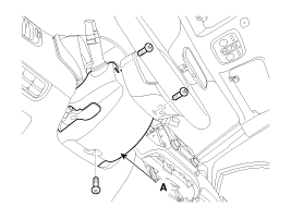
Disconnect the passenger`s airbag connectors (A).
|
|
5. |
Loosen the mounting bolt.
|
|
6. |
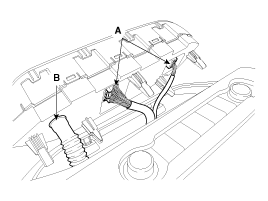
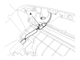
Using a screwdriver or remover, remove the photo sensor (A).
|
|
7. |
Disconnect the photo sensor connector (B).
|
|
8. |
After loosening the mounting bolts, nuts, screw, then remove the
main crash pad assembly (A).
|
|
9. |
Installation is the reverse of removal.
|
ŌĆó |
Make sure the crash pad fits onto the guide pins
correctly.
|
|
ŌĆó |
Before tightening the bolts, make sure the crash
pad wire harnesses are not pinched.
|
|
ŌĆó |
Make sure the connectors are plugged in properly,
and the antenna lead is connected properly.
|
|
ŌĆó |
Enter the anti- theft code for the radio, then
enter the customer`s radio station presets.
|
|
|
Cowl Cross Bar Replacement
| ŌĆó
|
A plastic trim tool is recommended, but if prying with
a screwdriver, wrap it with protective tape, and apply protective
tape around the related parts, to prevent damage.
|
| ŌĆó
|
Take care not to bend or scratch the trim and panels.
|
| ŌĆó
|
Put on gloves to protect your hands.
|
|
|
1. |
Remove the following items :
| A. |
Front seat
(Refer to the BD group ŌĆō ŌĆ£Front SeatŌĆØ)
|
| B. |
Front pillar trim
(Refer to the BD group ŌĆō ŌĆ£Interior TrimŌĆØ)
|
| C. |
Floor console assembly
(Refer to the BD group ŌĆō ŌĆ£ConsoleŌĆØ)
|
| D. |
(1)
1 . Main crash pad assembly
2 . Crash pad side cover [LH]
3 . Crash pad side cover [RH]
4 . Fuse box cover
5 . Crash pad lower panel
6 . Knee bolster panel
7 . St ...
Components
[General Type]
1 . Roof trim
2 . Sunvisor
3 . Retainer
4 . Assist handle bracket assembly
[Sunroof Type]
1 . Roof t ...
See also:Fuel Tank Air Filter
Removal
1.
Turn the ignition switch OFF and disconnect the battery negative
(-) cable.
2.
Lift the vehicle.
3.
...
Circuit Diagram (1)
...
Description
System Overview
The System offers the following features:
-
Human / machine interface through a 1-stage button, for terminal
switching and engine start.
...
Copyright ® www.kirmanual.com 2014-2025
| |


