 Kia Rio: Ignition Switch Assembly Removal
| 1. |
Disconnect the negative (-) battery terminal.
|
| 2. |
Remove the steering column upper and lower shrouds.
(Refer to the ST group - "Steering column")
|
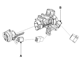
| 3. |
Disconnect the ignition switch connector (B) and the key switch
connector (A) from under the steering column.
|
| 4. |
If it is necessary to remove the key lock cylinder (A), remove
the key lock cylinder after pushing lock pin with key ACC.
|

 Ignition Switch Assembly Inspection
1.
Disconnect the ignition switch connector (B) and key switch connector
(A) from under the steering column.
2.
Check for continui ...
 Ignition Switch Assembly Installation
1.
Install the key lock cylinder.
When assembling, the key must be insert ...
See also:
Lubricants
Engine
Lubricants
Quantity
Gasoline 1.6(MT)
BJ
GRB006
80g
TJ
SH06 - VX21
LH:130g, RH:115g
...
Front Hub / Knuckle Inspection
1.
Check the hub for cracks and the splines for wear.
2.
Check the brake disc for scoring and damage.
3.
C ...
Door Switch Removal
1.
Remove the door switch (A) after loosening the bolt.
...
Categories
- Kia Rio Manuals Home
- Kia Rio YB 2017-2025 Owners Manual
- Kia Rio YB 2017-2025 Service Manual
- Kia Rio UB 2012-2017 Owners Manual
- Kia Rio UB 2012-2017 Service Manual
- Downloads

Copyright ® www.kirmanual.com 2014-2025