 Kia Rio: Inspection
Clutch Pedal Inspection
| 1. |
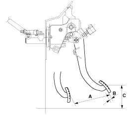
Measure the clutch pedal height (from the face of the pedal pad
to the floorboard) and the clutch pedal clevis pin play (measured at
the face of the pedal pad.)
|
Ignition Lock Switch Inspection
| 1. |
Disconnect 2P-connector from a ignition lock switch.
|
| 2. |
Disconnect the ignition lock switch. (if you can install a tester
with the switch fixed, this step can be omissible)
|
| 3. |
Check for continuity between terminals. (refer to the table below)
|

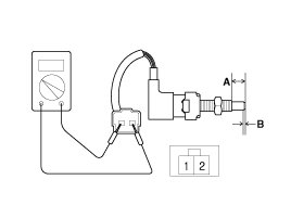
| 4. |
If there is difference between what tested and the table above,
replace the ignition lock switch with a new one.
|
 Components
1. Master cylinder
2. Ignition lock switch
3. Clutch switch
4. Pedal pad
...
 Removal
ŌĆó
Do not spill brake fluid on the vehicle; it may damage
the paint if brake fluid does ...
See also:
Towing
If the vehicle needs to be towed, call a professional towing service.
Never tow vehicle with just a rope or chain. It is very dangerous.
...
Removal
1.
Remove the under cover.
2.
Remove the mounting nut and disconnect the horn connector, then
remove the horn (A).
...
4Door Front Body B
Hood hinge mounting hole (Ø11)
Fender apron upper member tooling hole (Ø6.6)
Engine mounting hole (&O ...
Categories
- Kia Rio Manuals Home
- Kia Rio YB 2017-2025 Owners Manual
- Kia Rio YB 2017-2025 Service Manual
- Kia Rio UB 2012-2017 Owners Manual
- Kia Rio UB 2012-2017 Service Manual
- Downloads

Copyright ® www.kirmanual.com 2014-2025