
 Kia Rio: Manual Transaxle Removal
| 1. |
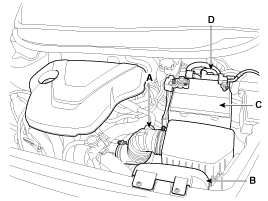
Remove the following items;
|
| 2. |
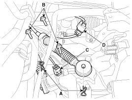
Remove the following items;
|
| 3. |
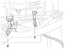
Remove the ground cable bolt (A) and tube bracket bolt (B).
|
| 4. |
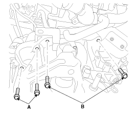
Remove the transaxle upper mounting bolt (B-2ea) and the start
motor mounting bolt (A-2ea).
|
| 5. |
Remove the cowl top cover.
(Refer to BD group.)
|
| 6. |
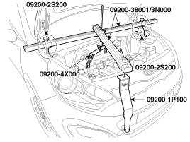
Using the engine support fixture (Support SST No.: 09200-2S200,
Adapter SST No.: 09200-1P000, 4X000, Beam SST No.: 09200-38001/3N000),
hold the engine and transaxle assembly safely.
|
| 7. |
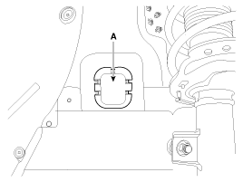
Remove the mounting cover (A).
|
| 8. |
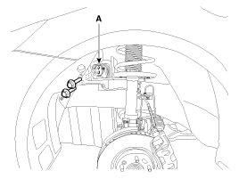
Remove the transaxle support mounting bracket bolts (A-2ea).
|
| 9. |
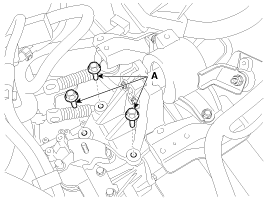
Remove the transaxle support mounting bracket bolts (A-3ea).
|
| 10. |
Lifting up the vehicle.
|
| 11. |
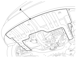
Remove the under cover (A).
|
| 12. |
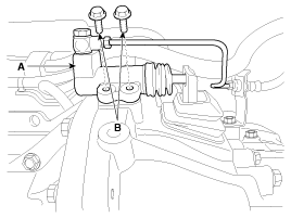
Remove the clutch release cylinder assembly (A) by removing bolts
(B-2ea).
|
| 13. |
Remove the drive shaft assembly.
(Refer to "Drive shaft assembly" in DS group.)
|
| 14. |
Remove the drive shaft cover (A).
|
| 15. |
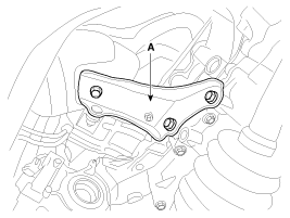
Remove the brackets (A).
|
| 16. |
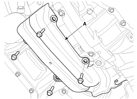
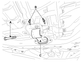
Remove the roll rod bracket (C) after removing bolt (A,B).
|
| 17. |
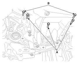
Remove the mounting bolts (A-3ea, B-2ea) of lower part of the
transaxle, and the left side cover and remove the transaxle assembly
by supporting it with a jack.
|

 Manual Transaxle Components
1. Transaxle support mounting bracket
2. Control shaft complete
3. Back up lamp switch
4. Vehicle speed sensor
...
 Manual Transaxle Installation
When replacing a clutch housing or transaxle assembly, the wiring
bracket should be installed in accordance with the clu ...
See also:
Windshield Glass Replacement
Removal
•
Put on gloves to protect your hands.
•
...
Line Pressure Control Solenoid Valve Description
line pressure control solenoid valve is attached to the valve body. This
variable force solenoid valve directly controls the hydraulic pressure inside
the line pressure.
...
Weight Classification System (WCS) Removal
1.
Disconnect the battery negative cable, and wait for at least three
minutes before beginning work.
2.
Remove the front passenger seat ass ...
Categories
- Kia Rio Manuals Home
- Kia Rio YB 2017-2025 Owners Manual
- Kia Rio YB 2017-2025 Service Manual
- Kia Rio UB 2012-2017 Owners Manual
- Kia Rio UB 2012-2017 Service Manual
- Downloads

Copyright © www.kirmanual.com 2014-2025