 Kia Rio: Removal
| ŌĆó
|
Use fender covers to avoid damaging painted surfaces.
|
| ŌĆó
|
To avoid damage, unplug the wiring connectors carefully
while holding the connector portion.
|
|
| ŌĆó
|
Mark all wiring and hoses to avoid misconnection.
|
| ŌĆó
|
To release the fuel system pressure before removing the
engine assembly, start the engine with the fuel pump relay removed.
And then turn off the ignition switch after engine stops.
|
|
|
1. |
Remove the engine cover (A).

|
|
2. |
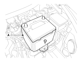
Disconnect the battery terminals (A). Disconnect the negative
terminal first.
Tightening torque
(+) terminal :
7.8 ~ 9.8N.m (0.8 ~ 1.0kgf.m, 5.8 ~ 7.2lb-ft)
(-) terminal (without battery sensor):
7.8 ~ 9.8N.m (0.8 ~ 1.0kgf.m, 5.8 ~ 7.2lb-ft)
(-) terminal (with battery sensor):
4.0 ~ 6.0N.m (0.4 ~ 0.6kgf.m, 3.0 ~ 4.4lb-ft)
|
|
|
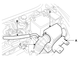
3. |
Remove the air cleaner assembly.
|
(1) |
Remove the air duct (A).
|
|
(2) |
Disconnect the breather hose (B).
|
|
(3) |
Disconnect the air intake hose (C) and then remove the
air cleaner assembly (D).
Tightening torque
Hose clamp bolt:
2.9 ~ 4.9N.m (0.3 ~ 0.5kgf.m, 2.2 ~ 3.6lb-ft)
Air cleaner assembly bolts:
7.8 ~ 9.8N.m (0.8 ~ 1.0kgf.m, 5.8 ~ 7.2lb-ft)
|
|
|
ŌĆó |
Install the air intake hose while the plate of
the hose clamp must be in line with the stopper of the
hose.
|
|
ŌĆó |
Install the air intake hose while the groove of
hose must be matched to the protrusion of the throttle
body.
|
|
|
|
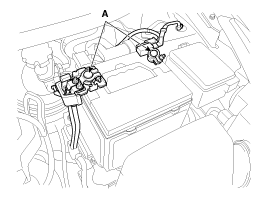
4. |
Remove the battery (A) after removing the mounting bracket.
Tightening torque:
8.8 ~ 13.7N.m (0.9 ~ 1.4kgf.m, 6.5 ~ 10.1lb-ft)
|
|
|
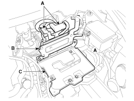
5. |
Disconnect the ECM connectors (A) and then remove the ECM (B)
and the battery tray (C).
Tightening torque
ECM bracket bolts & nut :
9.8 ~ 11.8 N.m (1.0 ~ 1.2 kgf.m, 7.2 ~ 8.7 lb-ft)
Battery tray bolts :
8.8 ~ 13.7N.m (0.9 ~ 1.4kgf.m, 6.5 ~ 10.1lb-ft)
|
|
|
6. |
Remove the under cover (A).
Tightening torque:
6.9 ~ 10.8 N.m (0.7 ~ 1.1 kgf.m, 5.1 ~ 8.0 lb-ft)
|
|
|
7. |
Loosen the drain plug, and drain the engine coolant. Remove the
radiator cap to drain with speed. (Refer to Cooling system in this group)
|
|
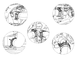
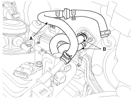
8. |
Disconnect the radiator upper hose (A) and lower hose (B).
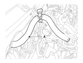
|
Install the radiator hoses as shown illustrations.
|
|
|
9. |
Recover the refrigerant and then remove the high pressure pipe
and low pressure pipe (A). (Refer to Air conditioning system in HA Group.)
|
|
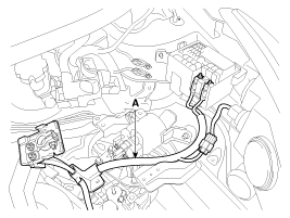
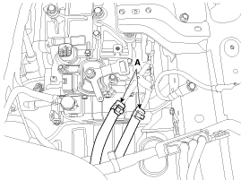
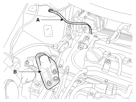
10. |
Disconnect the (+) cable (A) from the fuse/relay box.
|
|
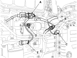
11. |
Disconnect the wiring connectors and harness clamps, and remove
the wiring and protectors from the cylinder head and intake manifold.
|
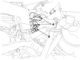
(1) |
The A/C compressor switch connector (A) and the alternator
connector (B)
|
|
(2) |
The intake OCV (Oil control valve) connector (A) and the
exhaust OCV (Oil control valve) connector (B)

|
|
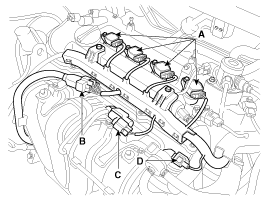
(3) |
The ignition coil connectors (A), the injector extension
connector (B), the VIS (Variable intake system) connector (C)
and the PCSV (Purge control solenoid valve) connector (D)
|
|
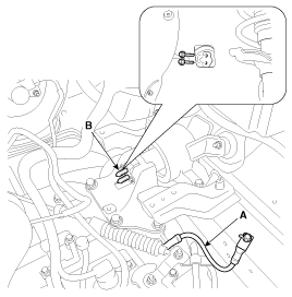
(4) |
The FPCV (Fuel pressure control valve) connector (A),
the intake CMPS (Camshaft position sensor) connector (B) and
the exhaust CMPS (Camshaft position sensor) connector (C)
|
|
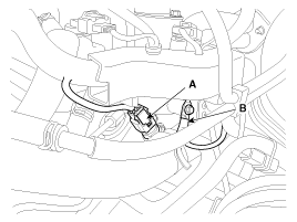
(5) |
The oxygen sensor connectors (A) and the condenser connector
(B)
|
|
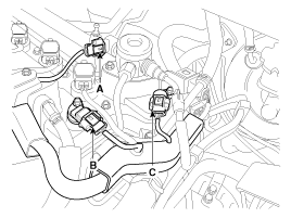
(6) |
The ECTS (Engine coolant temperature sensor) connector
(A) and the ground line (B)
|
|
(7) |
The ETC (Electronic throttle control) connector (A) and
the MAPS (Manifold absolute pressure sensor) & IATS (Intake
air temperature sensor) connector (B)

|
|
(8) |
The knock sensor connector (A), the CKPS (Crankshaft position
sensor) connector (B), the front connector (C), the starter
connector (D) and the oil pressure connector (E)
|
|
|
12. |
Remove the transaxle wire harness connectors and control cable
from the transaxle. (Refer to AT or MT group).
|
|
13. |
Disconnect the fuel hose (A) and the PCSV (Purge control solenoid
valve) hose (B).
|
|
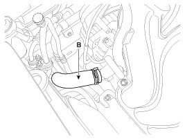
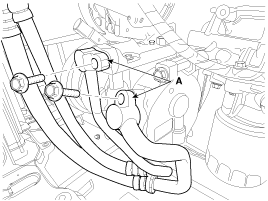
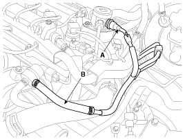
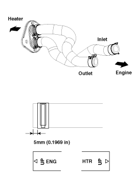
14. |
Disconnect the brake booster vacuum hose (A) and the heater hose
(B).
|
Install the heater hoses as shown illustrations.
|
|
|
15. |
Disconnect the ATF cooler hoses (A). (Refer to AT group)
|
|
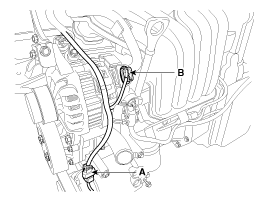
16. |
Remove the front muffler (A) after removing the rear oxygen sensor
connector from the bracket.
Tightening torque:
39.2 ~ 58.8 N.m (4.0 ~ 6.0 kgf.m, 28.9 ~ 43.4 lb-ft)
|
|
|
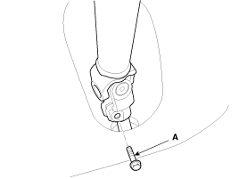
17. |
Remove the steering u-joint mounting bolt (A). (Refer to ST group)
|
|
18. |
Remove the front wheels. (Refer to SS group)
|
|
19. |
Remove the lower arms (A). (Refer to SS group)
|
|
20. |
Remove the stabilizer bar links (A). (Refer to SS group)
|
|
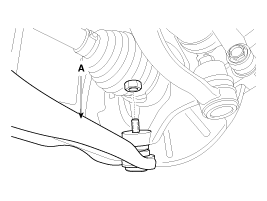
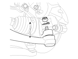
21. |
Remove the tie rod ends (A). (Refer to ST group)
|
|
22. |
Disconnect the drive shafts from the axle hubs. (Refer to DS group)
|
|
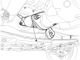
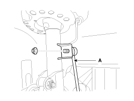
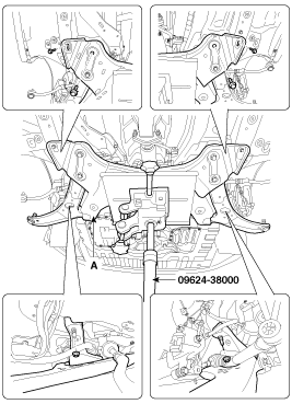
23. |
Remove the roll rod bracket (A).
Tightening torque
Nut (B) :
107.9 ~ 127.5 N.m (11.0 ~ 13.0 kgf.m, 79.6 ~ 94.0 lb-ft)
Bolt (C) :
49.0 ~ 63.7 N.m (5.0 ~ 6.5 kgf.m, 36.2 ~ 47.0 lb-ft)
|
|
|
24. |
Remove the roll rod mounting support bracket (A).
Tightening torque:
49.0 ~ 68.6 N.m (5.0 ~ 7.0 kgf.m, 36.2 ~ 50.6 lb-ft)
|
|
|
25. |
Support the sub frame (A) with a floor jack, and then remove the
sub frame mounting bolts and nuts. (Refer to SS group)
Tightening torque
Sub frame mounting bolts & nuts :
156.9 ~ 176.5 N.m (16.0 ~ 18.0 kgf.m, 115.7 ~ 130.2 lb-ft)
Sub frame stay mounting bolts :
44.1 ~ 53.9 N.m (4.5 ~ 5.5 kgf.m, 32.5 ~ 39.8 lb-ft)
|
|
ŌĆó |
After removing the sub frame mounting bolts and
nuts, the engine and transaxle assembly may fall downward.
Securely support the assemblies with floor jack.
|
|
ŌĆó |
Verify that the hoses and connectors are disconnected
before removing the engine and transaxle assembly.
|
|
|
|
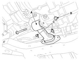
26. |
Disconnect the ground line (A) and then remove the engine mounting
support bracket (B).
Tightening torque
Ground line bolt :
10.8 ~ 13.7 N.m (1.1 ~ 1.4 kgf.m, 8.0 ~ 10.1 lb-ft)
Nut (C) :
63.7 ~ 83.4 N.m (6.5 ~ 8.5 kgf.m, 47.0 ~ 61.5 lb-ft)
Bolt (D) and nuts (E) :
49.0 ~ 63.7 N.m (5.0 ~ 6.5 kgf.m, 36.2 ~ 47.0 lb-ft)
|
|
|
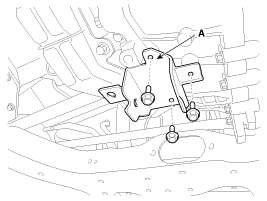
27. |
Disconnect the ground line (A), and then remove the transaxle
mounting bracket bolts (B).
Tightening torque:
88.3 ~ 107.9 N.m (9.0 ~ 11.0 kgf.m, 65.1 ~ 79.6 lb-ft)
|
|
|
28. |
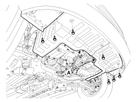
Remove the engine and transaxle assembly (A) by lifting vehicle.
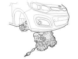
|
When removing the engine and transaxle assembly, be careful
not to damage any surrounding parts or body components.
|
|
1. Transaxle mounting bracket
2. Roll rod bracket
3. Engine mounting bracket
4. Engine mounting support bracket
...
Installation is in the reverse order of removal.
Perform the following :
ŌĆó
Adjust a shift cable.
ŌĆó
Refill engine with engine oil.
...
See also:
Head lamp leveling Actuator Installation
1.
Install the head lamp leveling actuator by turning the adjusting
gear.
2.
Install the head lamp assembly.
3.
...
Condenser Replacement
1.
Recover the refrigerant with a recovery/recycling/charging station.
2.
Disconnect the negative (-) battery terminal.
3.
...
Maintenance under severe usage conditions
The following items must be serviced more frequently on cars normally used under
severe driving conditions.
Refer to the chart below for the appropriate maintenance intervals.
R : Replace
I : I ...


 Components
 Installation