 Kia Rio: Removal
Engine removal is not required for this procedure.
|

Mark all wiring and hoses to avoid misconnection.
|

In case of removing the high pressure fuel pump, high pressure
fuel pipe, delivery pipe, and injector, there may be injury caused by
leakage of the high pressure fuel. So donŌĆÖt do any repair work right
after engine stops.
|

| 1. |
Remove the engine cover.
|
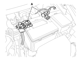
| 2. |
Disconnect the battery terminals (A).
|
| 3. |
Remove the air cleaner assembly.
|
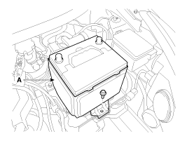
| 4. |
Remove the battery (A) after removing the mounting bracket.
|
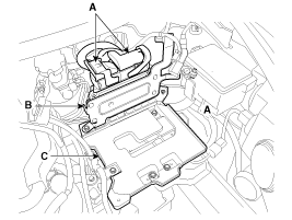
| 5. |
Disconnect the ECM connectors (A) and then remove the ECM (B)
and battery tray (C).
|
| 6. |
Remove the RH front wheel.
|
| 7. |
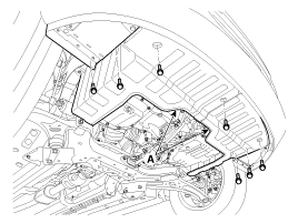
Remove the under covers (A).
|
| 8. |
Loosen the drain plug, and drain the engine coolant. Remove the
radiator cap to help drain the coolant faster. (Refer to Cooling system
in this group)
|
| 9. |
Disconnect the radiator upper hose (A) and lower hose (B).
|
| 10. |
Disconnect the wiring connectors and harness clamps, and remove
the wiring and protectors from the cylinder head and intake manifold.
|

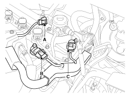
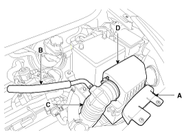
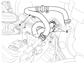
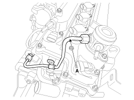
| 11. |
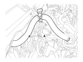
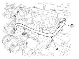
Disconnect the brake booster vacuum hose (A) and heater hose (B).
|
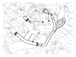
| 12. |
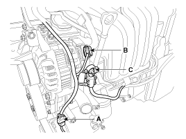
Disconnect the fuel hose (A), the PCV (Positive crankcase ventilation)
hose (B) and the PCSV (Purge control solenoid valve) hose (C).
|
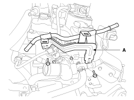
| 13. |
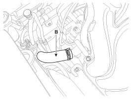
Remove the vacuum pipe assembly (A).
|
| 14. |
Remove the high pressure pipe (A). (Refer to FL group)
|
| 15. |
Remove the high pressure fuel pump (A) and the roller tappet (B).
(Refer to FL group)
|

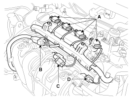
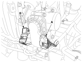
| 16. |
Remove the ignition coils (A).
|

| 17. |
Remove the exhaust OCV (Oil control valve) (B).
|

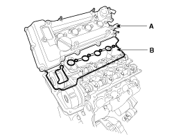
| 18. |
Remove the cylinder head cover (A) with gaskets (B).
|
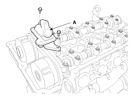
| 19. |
Remove the exhaust OCV (Oil control valve) adapter (A).
|
| 20. |
Remove the timing chain.
(Refer to Timing system in this group)
|
| 21. |
Remove the exhaust manifold assembly. (Refer to Intake and exhaust
system in this group)
|
| 22. |
Remove the intake manifold module assembly. (Refer to Intake and
exhaust system in this group)
|
| 23. |
Remove the intake continous variable vavle timing (CVVT) assembly
(A) and exhaust continous variable vavle timing (CVVT) assembly (B).
|

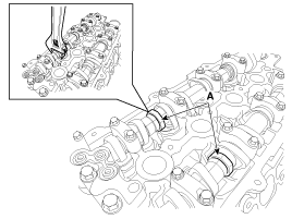
| 24. |
Remove the camshaft bearing caps (A) with the order below.
|
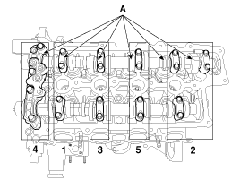
| 25. |
Remove the camshafts (A).
|
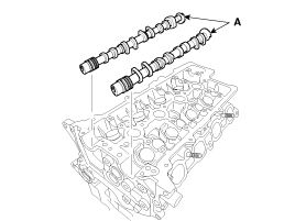
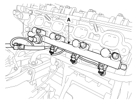
| 26. |
Remove the injector & rail assembly (A). (Refer to FL group)
|
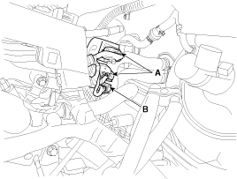
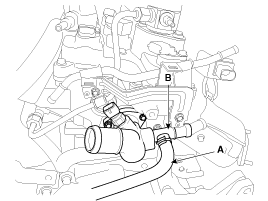
| 27. |
Remove the water temperature control assembly (B) after disconnecting
the throttle body cooling hose (A).
|
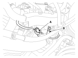
| 28. |
Remove the heater pipe (A).
|
| 29. |
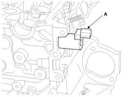
Remove the intake OCV (Oil Control Valve) (A).
|
| 30. |
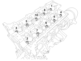
Remove the cylinder head bolts, then remove the cylinder head.
|
 Components
1. Cylinder head cover
2. Cylinder head cover gasket
3. Cylinder head assembly
4. Cylinder head gasket
5. Camshaft position sensor
6. Camshaft bearing cap
7. Camshaft ...
 Disassembly
Identify MLA(Mechanical lash adjuster), valves, valve springs
as they are removed so that each item can be reinstalled i ...
See also:
Electric Oil Pump: Removal
1.
Disconnect the negative (-) battery terminal.
2.
Disconnect the Electric Oil Pump (EOP) connector (A).
3.
...
Components
1. Battery (Non-ISG Type)
2. Battery (ISG Type)
3. Battery tray
4. Battery insulation pad
5. Battery mounting bracket
...
Heater & A/C Control Unit (FATC) Components
Connector Pin Function
Connector
Pin No
Function
Connector
Pin No
Function
A
1
IGN 2
B
17
HI-SCAN (K-L ...
Categories
- Kia Rio Manuals Home
- Kia Rio YB 2017-2025 Owners Manual
- Kia Rio YB 2017-2025 Service Manual
- Kia Rio UB 2012-2017 Owners Manual
- Kia Rio UB 2012-2017 Service Manual
- Downloads

Copyright ® www.kirmanual.com 2014-2025