 Kia Rio: Inspection
| Connecting Rod And Crankshaft |
|
1. |
Check the connecting rod end play.
Using feeler gauge, measure the end play while moving the connecting
rod back and forth.
End play
Standard : 0.10 ~ 0.25mm (0.0039 ~ 0.0098in)
Maximum : 0.35mm (0.0138in)
|
| A. |
If out-of-tolerance, install a new connecting rod.
|
| B. |
If still out-of-tolerance after connecting rod replacement,
replace the crankshaft.
|
|
|
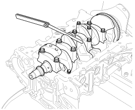
2. |
Check the connecting rod bearing oil clearance.
|
(1) |
Check the match marks on the connecting rod and cap are
aligned to ensure correct reassembly.
|
|
(2) |
Remove the 2 connecting rod cap bolts.
|
|
(3) |
Remove the connecting rod cap and lower bearing.
|
|
(4) |
Clean the crankshaft pin journal and bearing.
|
|
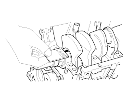
(5) |
Place a plastigage across the crankshaft pin journal.
|
|
(6) |
Reinstall the lower bearing and cap, and tighten the bolts.
Do not reuse the bolts.
Tightening torque :
17.7 ~ 21.6N.m (1.8 ~ 2.2kgf.m, 13.0 ~ 15.9lb-ft)
+ 88 ~ 92┬░
|
|
ŌĆó |
Always use new connecting rod cap bolts.
Connecting rod cap bolts are toque-to-yield
bolts designed to be permanently elongated beyond
the state of elasticity when torqued, so if
the bolts are removed and reused, it may cause
the bolts to break or fail to maintain clamping
force.
|
|
ŌĆó |
Do not turn the crankshaft.
|
|
|
|
(7) |
Remove the 2 bolts, connecting rod cap and lower bearing
.
|
|
(8) |
Measure the plastigage at its widest point.
Standard oil clearance
0.032 ~ 0.052mm (0.0013 ~ 0.0020in)
|
|
|
(9) |
If the measurement from the plastigage is too wide or
too narrow, remove the upper and lower bearing and then install
a new bearings with the same color mark.
Recheck the oil clearance.
|
Do not file, shim, of scrape the bearings or the
caps to adjust clearance.
|
|
|
(10) |
If the plastigage shows the clearance is still incorrect,
try the next larger or smaller bearing.
Recheck the oil clearance.
|
If the proper clearance cannot be obtained by
using the appropriate larger or smaller bearings, replace
the crankshaft and restart over.
|
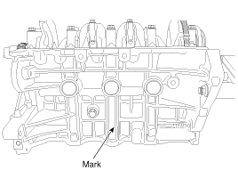
|
If the marks are indecipherable because of an
accumulation of dirt and dust, do not scrub them with
a wire brush or scraper. Clean them only with solvent
or detergent.
|
Connecting Rod Mark Location
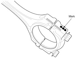
Discrimination Of Connecting Rod
Mark
|
Connecting rod big-end
inner diameter
|
A, 0
|
45.000 ~ 45.006mm (1.7717 ~ 1.7719in)
|
B, 00
|
45.006 ~ 45.012mm (1.7719 ~ 1.7721in)
|
C, 000
|
45.012 ~ 45.018mm (1.7721 ~ 1.7724in)
|
Crankshaft Pin Diameter Mark Location
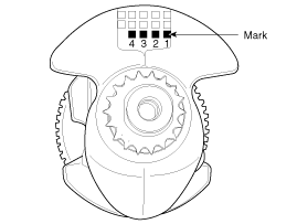
Discrimination Of Crankshaft Pin Diameter
Mark
|
Crankshaft pin outer diameter
|
1
|
41.972 ~ 41.966mm (1.6524 ~ 1.6522in)
|
2
|
41.966 ~ 41.960mm (1.6522 ~ 1.6520in)
|
3
|
41.960 ~ 41.954mm (1.6520 ~ 1.6517in)
|
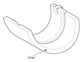
Connecting Rod Bearing Color Location
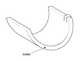
Discrimination Of Connecting Rod Bearing
Mark
|
Color
|
Connecting rod bearing thickness
|
A
|
Blue
|
1.514 ~ 1.517mm (0.0596 ~ 0.0597in)
|
B
|
Black
|
1.511 ~ 1.514mm (0.0595 ~ 0.0596in)
|
C
|
None
|
1.508 ~ 1.511mm (0.0594 ~ 0.0595in)
|
D
|
Green
|
1.505 ~ 1.508mm (0.0593 ~ 0.0594in)
|
E
|
Red
|
1.502 ~ 1.505mm (0.0591 ~ 0.0593in)
|
|
|
(11) |
Select the bearing by using selection table.
Connecting Rod Bearing Selection Table
|
Connecting rod mark
|
A, 0
|
B, 00
|
C, 000
|
Crank shaft pin journal mark
|
1
|
E
(Red)
|
D
(Green)
|
C
(None)
|
2
|
D
(Green)
|
C
(None)
|
B
(Black)
|
3
|
C
(None)
|
B
(Black)
|
A
(Blue)
|
|
|
|
3. |
Check the connecting rods.
|
(1) |
When reinstalling, make sure that cylinder numbers put
on the connecting rod and cap at disassembly match. When a new
connecting rod is installed, make sure that the notches for
holding the bearing in place are on the same side.
|
|
(2) |
Replace the connecting rod if it is damaged on the thrust
faces at either end. Also if step wear or a severely rough surface
of the inside diameter of the small end is apparent, the rod
must be replaced as well.
|
|
(3) |
Using a connecting rod aligning tool, check the rod for
bend and twist. If the measured value is close to the repair
limit, correct the rod by a press. Any connecting rod that has
been severely bent or distorted should be replaced.
Allowable bend of connecting
rod :
0.05mm / 100mm (0.0020in / 3.94in ) or less
Allowable twist of connecting
rod :
0.10mm / 100mm (0.0039in / 3.94in) or less
|
|
When the connecting rods installed without bearings,
there should be no difference on side surface.
|
|
|
|
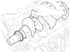
4. |
Check the crankshaft bearing oil clearance.
|
(1) |
To check main bearing-to-journal oil clearance, remove
the main bearing caps and lower bearings.
|
|
(2) |
Clean each main journal and lower bearing with a clean
shop towel.
|
|
(3) |
Place one strip of plastigage across each main journal.
|
|
(4) |
Reinstall the lower bearings and caps, then tighten the
bolts.
Tightening torque :
17.7~21.6Nm (1.8~2.2kgf.m, 13.0~15.9lb-ft) + 88~92┬░
|
|
ŌĆó |
Always use new crankshaft main bearing
cap bolts. Crankshaft main bearing cap bolts
are toque-to-yield bolts designed to be permanently
elongated beyond the state of elasticity when
torqued, so if the bolts are removed and reused,
it may cause the bolts to break or fail to maintain
clamping force.
|
|
ŌĆó |
Do not turn the crankshaft.
|
|
|
|
(5) |
Remove the cap and lower bearing again, and measure the
widest part of the plastigage.
Standard oil clearance
:
No.1, 2, 3, 4, 5 : 0.021 ~ 0.042mm (0.0008 ~ 0.0017in)
|
|
|
(6) |
If the plastigage measures too wide or too narrow, remove
the upper and lower bearing and then install a new bearings
with the same color mark. (Refer to crankshaft main bearing
selection table in this Group).
Recheck the oil clearance.
|
Do not file, shim, or scrape the bearings or the
cap to adjust clearance.
|
|
|
(7) |
If the plastigage shows the clearance is still incorrect,
try the next larger or smaller bearing. (Refer to crankshaft
main bearing selection table in this Group).
Recheck the oil clearance.
|
If the proper clearance cannot be obtained by
using the appropriate larger or smaller bearings, replace
the crankshaft and start over.
|
|
If the marks are indecipherable because of an
accumulation of dirt and dust, do not scrub them with
a wire brush or scraper. Clean them only with solvent
or detergent.
|
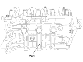
Cylinder block crankshaft journal
bore mark location
Letters have been stamped on the side surface of the block
as a mark for the size of each of the 5 main journal bores.
Use them, and the numbers or letters stamped on the crank
(marks for main journal size), to choose the correct bearings.
Discrimination Of Cylinder Block Crankshaft Journal Bore
Mark
|
Cylinder block crankshaft journal
bore
inner diameter
|
A
|
52.000 ~ 52.006mm (2.0472 ~ 2.0475in)
|
B
|
52.006 ~ 52.012mm (2.0475 ~ 2.0477in)
|
C
|
52.012 ~ 52.018mm (2.0477 ~ 2.0479in)
|
Crankshaft Main Journal Mark Location
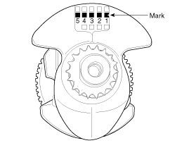
Discrimination Of Crankshaft Main Journal
Mark
|
Crankshaft main journal
outer diameter
|
1
|
47.960 ~ 47.954mm (1.8882 ~ 1.8879in)
|
2
|
47.954 ~ 47.948mm (1.8879 ~ 1.8877in)
|
3
|
47.948 ~ 47.942mm (1.8877 ~ 1.8875in)
|
Crankshaft Main Bearing Color Location
Discrimination Of Crankshaft Main Bearing
Mark
|
Color
|
Crankshaft main bearing thickness
|
No.1, 2, 3, 4, 5
|
A
|
Blue
|
2.026 ~ 2.029mm (0.0798 ~ 0.0799in)
|
B
|
Black
|
2.023 ~ 2.026mm (0.0796 ~ 0.0798in)
|
C
|
None
|
2.020 ~ 2.023mm (0.0795 ~ 0.0796in)
|
D
|
Green
|
2.017 ~ 2.020mm (0.0794 ~ 0.0795in)
|
E
|
Red
|
2.014 ~ 2.017mm (0.0793 ~ 0.0794in)
|
|
|
(8) |
Select the bearing by using selection table.
Crankshaft Main Bearing Selection Table
|
Cylinder block crankshaft journal
bore mark
|
A
|
B
|
C
|
Crank shaft main journal mark
|
1
|
E
(Red)
|
D
(Green)
|
C
(None)
|
2
|
D
(Green)
|
C
(None)
|
B
(Black)
|
3
|
C
(None)
|
B
(Black)
|
A
(Blue)
|
|
|
|
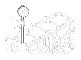
5. |
Check the crankshaft end play.
Using a dial indicator, measure the thrust clearance while prying
the crankshaft back and forth with a screwdriver.
End play
Standard: 0.05 ~ 0.25mm (0.0020 ~ 0.0098in)
Limit : 0.30mm (0.0118in)
|
If the end play is greater than maximum, replace the center bearing.
|
Cylinder Block
|
1. |
Remove the gasket material.
Using a gasket scraper, remove all the gasket material from the
top surface of the cylinder block.
|
|
2. |
Clean the cylinder block
Using a soft brush and solvent, thoroughly clean the cylinder
block.
|
|
3. |
Inspect the top surface of cylinder block for flatness.
Using a precision straight edge and feeler gauge, measure the
surface contacting the cylinder head gasket for warpage.
Flatness of cylinder block gasket surface
Standard :
Less than 0.05mm (0.0020in) for total area
Less than 0.02mm (0.0008in) for a section of 100mm (3.9370in)
X 100mm (3.9370in)
|

|
|
4. |
Inspect the cylinder bore.
Visually check the cylinder for vertical scratchs.
If deep scratchs are present, replace the cylinder block.
|
|
5. |
Inspect the cylinder bore diameter.
Using a cylinder bore gauge, measure the cylinder bore diameter
at position in the thrust and axial direction.
Standard diameter :
77.00 ~ 77.03mm (3.0315 ~ 3.0327in)
|
|
|
6. |
Check the cylinder bore size code on the cylinder block side surface.
Discrimination Of Cylinder Bore Size
Mark
|
Cylinder bore inner diameter
|
A
|
77.00 ~ 77.01mm (3.0315 ~ 3.0319in)
|
B
|
77.01 ~ 77.02mm (3.0319 ~ 3.0323in)
|
C
|
77.02 ~ 77.03mm (3.0323 ~ 3.0327in)
|
|
|
7. |
Check the piston size mark (A) on the piston top face.
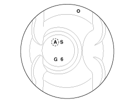
A : Grade
S : ISG type
G : Gasoline engine
6 : 1.6L
Discrimination Of Piston Outer Diameter
Mark
|
Piston outer diameter
|
A
|
76.97 ~ 76.98mm (3.0303 ~ 3.0307in)
|
B
|
76.98 ~ 76.99mm (3.0307 ~ 3.0311in)
|
C
|
76.99 ~ 77.00mm (3.0311 ~ 3.0315in)
|
|
|
8. |
Select the piston related to cylinder bore class.
Piston -to-cylinder clearance
:
0.02 ~ 0.04mm (0.0008 ~ 0.0016in)
|
|
Piston And Piston Rings
|
1. |
Clean the piston.
|
(1) |
Using a gasket scraper, remove the carbon from the piston
top.
|
|
(2) |
Using a groove cleaning tool or broken ring, clean the
piston ring grooves.
|
|
(3) |
Using solvent and a brush, thoroughly clean the piston.
|
|
|
2. |
The standard measurement of the piston outside diameter is taken
12mm(0.4724in) from bottom land of the piston.
Standard diameter :
76.97 ~ 77.00mm (3.0303 ~ 3.0315in)
|
|
|
3. |
Calculate the difference between the cylinder bore inner diameter
and the piston outer diameter.
Piston-to-cylinder clearance
:
0.02 ~ 0.04mm (0.0008 ~ 0.0016in)
|
|
|
4. |
Inspect the piston ring side clearance.
Using a feeler gauge, measure the clearance between new piston
ring and the wall of ring groove.
Piston ring side clearance
No.1 ring : 0.04 ~ 0.08mm (0.0016 ~ 0.0031in)
No.2 ring : 0.04 ~ 0.08mm (0.0016 ~ 0.0031in)
Oil ring : 0.02 ~ 0.06mm (0.0008 ~ 0.0024in)
Limit
No.1 ring : 0.1mm (0.0039in)
No.2 ring : 0.1mm ( 0.0039in)
Oil ring : 0.2mm ( 0.0079in)
|
If the clearance is greater than maximum, replace the piston.
|
|
5. |
Inspect the piston ring end gap.
To measure the piston ring end gap, insert a piston ring into
the cylinder bore. Position the ring at right angles to the cylinder
wall by gently pressing it down with a piston. Measure the gap with
a feeler gauge. If the gap exceeds the service limit, replace the piston
rings. If the gap is too large, recheck the cylinder bore inner diameter.
If the bore is over the service limit, the cylinder block must be rebored.
Piston ring end gap
Standard
No.1 ring : 0.14 ~ 0.28mm (0.0079 ~ 0.0138in)
No.2 ring : 0.30 ~ 0.45mm (0.0118 ~ 0.0177in)
Oil ring : 0.20 ~ 0.40mm(0.0079 ~ 0.0157in)
Limit
No.1 ring : 0.3mm(0.0118in)
No.2 ring : 0.5mm(0.0197in)
Oil ring : 0.8mm(0.0315in)
|
|
Piston Pins
|
1. |
Measure the outer diameter of piston pin
Piston pin diameter :
18.001 ~ 18.006mm (0.7087 ~ 0.7089in)
|
|
Engine removal is required for this procedure. (Refer to Engine and transaxle
assembly removal in this group)
1.
M/T : Remove the fly wheel.
2.
...
ŌĆó
Thoroughly clean all parts to assembled.
ŌĆó
...
See also:
Voice recognition
Using Voice Recognition
Starting Voice Recognition
Shortly press the
key on the steering wheel.
Say a command
If prompt feedback is in [ON], then the system will say ŌĆ£Please say a com ...
Specification
Item
Bulb Watt (W)
Bulb Type
Front
Head lamp (High)
60/55
H1
Head lamp (Low)
60/55
H7
Position lmap
...
Precautions
General Precautions
Please read the following precautions carefully before performing the
airbag system service.
Observe the instructions described in this manual, or the airba ...


 Disassembly
 Reassembly