
 Kia Rio: Instrument Cluster Components

| Pin No. |
Description |
Pin No. |
Description |
| 1 |
Cluster ground |
21 |
S ground |
| 2 |
P ground |
22 |
Fuel (-) |
| 3 |
Rheostat output |
23 |
- |
| 4 |
Rheostat detent output |
24 |
DC-DC (ISG) |
| 5 |
ALT L output |
25 |
Battery (+) |
| 6 |
High beam (+) |
26 |
Ignition 1 |
| 7 |
4P output |
27 |
Speed |
| 8 |
AT P output |
28 |
- |
| 9 |
AT N output |
29 |
C_CAN_HIGH |
| 10 |
AT D output |
30 |
C_CAN_LOW |
| 11 |
Fuel input |
31 |
B_CAN_LOW |
| 12 |
- |
32 |
B_CAN_HIGH |
| 13 |
Parking brake |
33 |
Rheostat up |
| 14 |
Airbag supply |
34 |
Rheostat down |
| 15 |
Check engine |
35 |
Cluster signal |
| 16 |
Water seperator |
36 |
Active ECO |
| 17 |
- |
37 |
- |
| 18 |
Immobilizer |
38 |
Oil pressure |
| 19 |
Key out |
39 |
Battery charge |
| 20 |
Wahser low |
40 |
Illumination (+) |
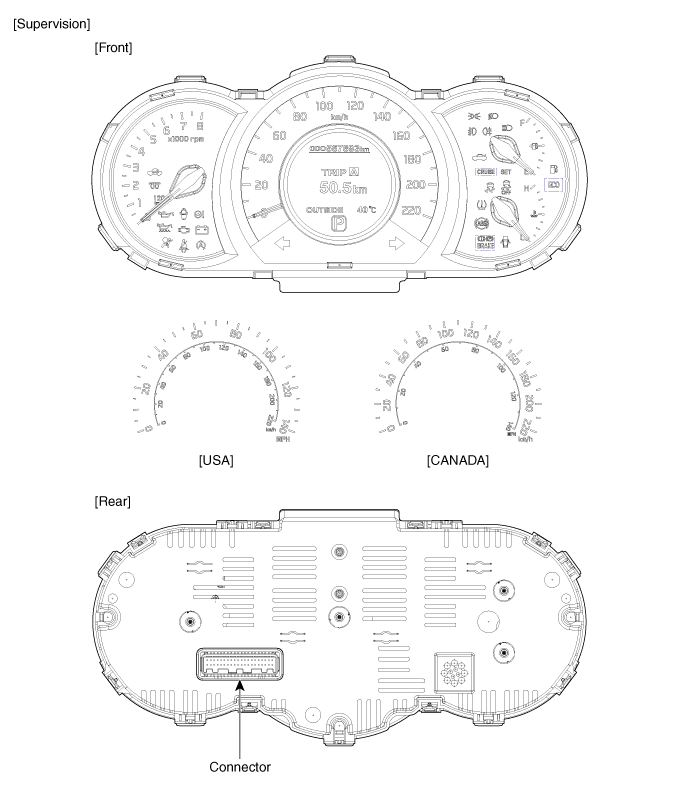
| Pin No. |
Description |
Pin No. |
Description |
| 1 |
Cluster ground |
21 |
S ground |
| 2 |
P ground |
22 |
Fuel (-) |
| 3 |
Rheostat output |
23 |
- |
| 4 |
Rheostat detent output |
24 |
DC-DC (ISG) |
| 5 |
ALT L output |
25 |
Battery (+) |
| 6 |
High beam (+) |
26 |
Ignition 1 |
| 7 |
4P output |
27 |
Speed |
| 8 |
AT P output |
28 |
- |
| 9 |
AT N output |
29 |
C_CAN_HIGH |
| 10 |
AT D output |
30 |
C_CAN_LOW |
| 11 |
Fuel input |
31 |
B_CAN_LOW |
| 12 |
- |
32 |
B_CAN_HIGH |
| 13 |
Parking brake |
33 |
Rheostat up |
| 14 |
Airbag supply |
34 |
Rheostat down |
| 15 |
Check engine |
35 |
Cluster signal |
| 16 |
Water seperator |
36 |
Active ECO |
| 17 |
- |
37 |
- |
| 18 |
Immobilizer |
38 |
Oil pressure |
| 19 |
- |
39 |
Battery charge |
| 20 |
Wahser low |
40 |
Illumination (+) |
 Component Location
1. Instrument cluster assembly
2. Seat belt switch
3. Vehicle speed sensor
4. Engine coolant temperature sender
5. Oil pressure switch
6. Brake fluid level warning switch
...
 Instrument Cluster Circuit Diagram
[Standard]
[Supervision]
...
See also:
Schematic Diagrams
Circuit Diagram (1)
Circuit Diagram (2)
Circuit Diagram (3)
SRSCM Connector Terminal
Pin
Function (Connector A)
Pin
Function (Connector B)
...
Mode Control Actuator Description
The mode control actuator is located at the heater unit.
It adjusts position of mode door by operating mode control actuator based
on signal of A/C control unit. Pressing mode select switch ...
Instrument Cluster Installation
1.
Connect the cluster connector.
2.
Install the cluster assembly.
3.
Install the center fascia panel.
...
Categories
- Kia Rio Manuals Home
- Kia Rio YB 2017-2026 Owners Manual
- Kia Rio YB 2017-2026 Service Manual
- Kia Rio UB 2012-2017 Owners Manual
- Kia Rio UB 2012-2017 Service Manual
- Downloads

Copyright © www.kirmanual.com 2014-2026