 Kia Rio: Description
The charging system included a battery, an alternator with a built-in
regulator, and the charging indicator light and wire.
The Alternator has eight built-in diodes, each rectifying AC current to
DC current.
Therefore, DC current appears at alternator "B" terminal.
In addition, the charging voltage of this alternator is regulated by the
battery voltage detection system.
The alternator is regulated by the battery voltage detection system. The
main components of the alternator are the rotor, stator, rectifier, capacitor
brushes, bearings and V-ribbed belt pulley. The brush holder contains a built-in
electronic voltage regulator.
[AMS type (OAD)]
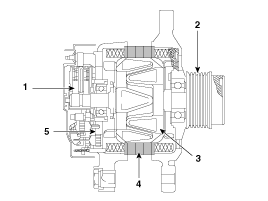
| 1. Brush 2. OAD (Overrunning Alternator Decoupler) 3. Rotor 4. Stator 5. Rectifier |
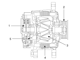
[AMS type (NON-OAD)]
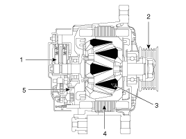
[ISG type (NON-DAD)]
| 1. Brush 2. Drive belt pulley 3. Rotor 4. Stator 5. Rectifier |
| Alternator Management System |
Alternator management system controls the charging voltage set point in
order to improve fuel economy, manage alternator load under various operating
conditions, keep the battery charged, and protect the battery from over-charging.
ECM controls generating voltage by duty cycle (charging control, discharging
control, normal control) based on the battery conditions and vehicle operating
conditions.
The system conducts discharging control when accelerating a vehicle. Vehicle
reduces an alternator load and consumes an electric power form a battery.
The system conducts charging control when decelerating a vehicle. Vehicle
increases an alternator load and charges a battery.
 Charging System
...
 On-vehicle Inpection
ŌĆó
First of all, check for DTCs. If a DTC is present, perform
troubleshooting in accord ...
See also:
Voice recognition
Using Voice Recognition
Starting Voice Recognition
Shortly press the
key on the steering wheel.
Say a command
If prompt feedback is in [ON], then the system will say ŌĆ£Please say a com ...
SS-A Solenoid Valve(ON/OFF) Removal
1.
Remove the battery and the battery tray.
(Refer to "Charging system" in EE group.)
2.
Remove the under cover (A).
...
Components
1. Clutch release fork
2. Clutch cover assembly
3. Clutch disk assembly
4. Clutch release bearing
...
Categories
- Kia Rio Manuals Home
- Kia Rio YB 2017-2026 Owners Manual
- Kia Rio YB 2017-2026 Service Manual
- Kia Rio UB 2012-2017 Owners Manual
- Kia Rio UB 2012-2017 Service Manual
- Downloads

Copyright ® www.kirmanual.com 2014-2026