 Kia Rio: Front Driveshaft Replacement
| 1. |
Loosen the wheel nuts slightly.
Raise the vehicle, and make sure it is securely supported.
|
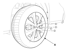
| 2. |
Remove the front wheel and tire (A) from front hub.
|

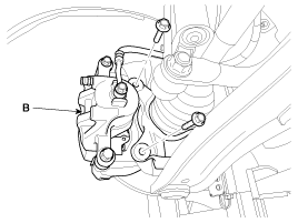
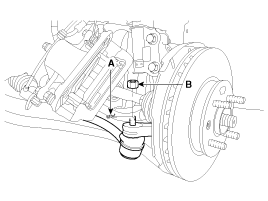
| 3. |
Remove the brake caliper mounting bolts, and then hold the brake
caliper assembly (B) with wire.
|
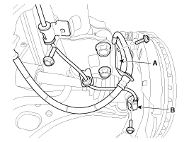
| 4. |
Remove the brake hose bracket (A) & wheel speed sensor (B).
|
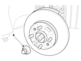
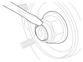
| 5. |
Remove driveshaft nut (A) from the front hub after applying the
brake.
|
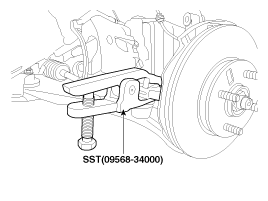
| 6. |
Remove the tie rod end ball joint from the knuckle by using the
SST(09568-34000).
|
| 7. |
Remove the lower arm (A) from the knuckle.
|
| 8. |
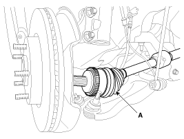
Disconnect the driveshaft (A) from the front hub assembly.
|
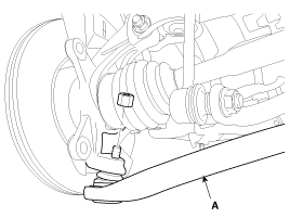
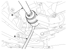
| 9. |
Insert a pry bar (A) between the transaxle case and joint case,
and separate the drive shaft (B) from the transaxle case.
|
| 10. |
Install in the reverse order of removal.
|
 Front Driveshaft Component
1. Driveshaft (LH)
2. Circlip
3. Circlip
4. Driveshaft (RH)
...
 Front Driveshaft Inspection
1.
Check the driveshaft boots for damage and deterioration.
2.
Check the driveshaft spline for wear or damage.
3.
...
See also:
Specification
Accelerator
Position
Output Voltage (V)
APS1
APS2
C.T
0.7 ~ 0.8
0.275 ~ 0.475
W.O.T
3.8 ~ 4.4
1.75 ~ 2.35 ...
Components
...
Transaxle Control Module (TCM) Description
Transaxle Control Module (TCM) is the automatic transaxle's brain. The
module receives and processes signals from various sensors and implements a
wide range of transaxle controls to ensu ...
Categories
- Kia Rio Manuals Home
- Kia Rio YB 2017-2026 Owners Manual
- Kia Rio YB 2017-2026 Service Manual
- Kia Rio UB 2012-2017 Owners Manual
- Kia Rio UB 2012-2017 Service Manual
- Downloads

Copyright ® www.kirmanual.com 2014-2026