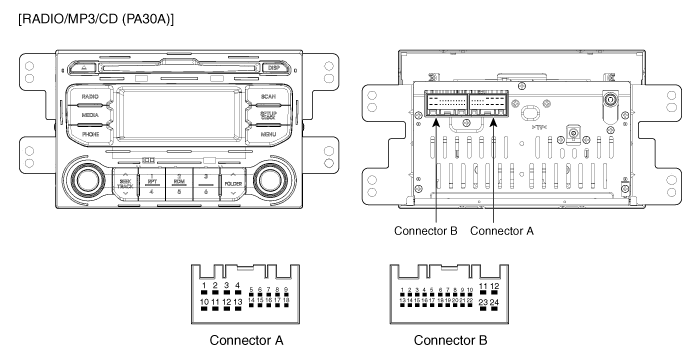
 Kia Rio: Audio Unit Components

Terminal specification(PA30A)
| No |
Terminal Description |
Condition |
Specified Condition |
| A1 |
Loudspeaker Rear Left+ |
Needed connection to the car |
Analog output |
| A2 |
Loudspeaker Front Left+ |
Needed connection to the car |
Analog output |
| A3 |
Loudspeaker Front Right+ |
Needed connection to the car |
Analog output |
| A4 |
Loudspeaker Rear Right+ |
Needed connection to the car |
Analog output |
| A5 |
- |
|
|
| A6 |
- |
|
|
| A7 |
- |
|
|
| A8 |
Rheostat from vehicle + |
Needed connection to the car |
|
| A9 |
ILL DIM CANCEL |
Needed connection to the car |
|
| A10 |
Loudspeaker Rear Left- |
Needed connection to the car |
Analog output |
| A11 |
Loudspeaker Front Left- |
Needed connection to the car |
Analog output |
| A12 |
Loudspeaker Front Right- |
Needed connection to the car |
Analog output |
| A13 |
Loudspeaker Rear Right- |
Needed connection to the car |
Analog output |
| A14 |
- |
|
|
| A15 |
- |
|
|
| A16 |
- |
|
|
| A17 |
Rheostat from vehicle - |
Needed connection to the car |
|
| A18 |
Remote Power supply for Antenna |
Acc on |
9V ~ 18V |
| B1 |
- |
|
|
| B2 |
- |
|
|
| B3 |
- |
|
|
| B4 |
Steering Wheel Remote Control |
Steering Wheel switch pushed |
0.5V ~ 3V |
| B5 |
- |
|
|
| B6 |
USB D+ |
USB device is inserted |
3.2V ~ 3.45 |
| B7 |
USB /iPod power |
USB/iPod device is inserted |
4.9V ~ 5.1V |
| B8 |
AUX Right Sound Signal |
External Auxiliary device is Audio playing (At time of Aux jack use) |
A waveform synchronized with sound is output |
| B9 |
AUX Reference Ground |
Always |
Below 1 ohm |
| B10 |
Bluetooth MIC+ |
Input the Voice Signal via MIC |
A waveform synchronized with Voice data via MIC |
| B11 |
Accessory |
Engine switch on(ACC) |
11 ~ 14 V |
| B12 |
Battery |
Always |
11 ~ 14 V |
| B13 |
- |
|
|
| B14 |
- |
|
|
| B15 |
- |
|
|
| B16 |
Speed Sensor Signal |
Engine switch on(IGN), car is moved slowly |
Approx. 5V Level Pulse Generation |
| B17 |
Steering Wheel Remote Control Gnd |
Always |
Below 1 ohm |
| B18 |
USB D- |
USB device is inserted |
3.2V ~ 3.45 |
| B19 |
iPod detection line |
iPod device is inserted |
GND |
| B20 |
AUX Signal Input Detect |
Auxiliary device is inserted |
0V(Low) → 5V(High) |
| B21 |
AUX Left Sound Signal |
External Auxiliary device is Audio playing (At time of Aux jack use) |
A waveform synchronized with sound is output |
| B22 |
Bluetooth MIC- |
Input the Voice Signal via MIC |
A waveform synchronized with Voice data via MIC |
| B23 |
- |
|
|
| B24 |
Ground |
Always |
Below 1 ohm |

 Components Location
1. Audio unit
2. Tweeter speaker
3. Roof antenna (Radio + SDARS)
4. Antenna cable connector
5. Front door speaker
6. Rear door speaker
7. Antenna feeder cable
...
 Audio Unit Schematic Diagrams
System Block Diagram
...
See also:
Rear Wheel Alignment
When using a commercially available computerized wheel alignment
equipment to inspect the rear wheel alignment, always p ...
Hood switch Description
The hood switch is included as the influencing factors in the calculation
of the ISG function. If the hood is open, the engine must not be started or
stopped by the ISG function for safety re ...
Door Switch Installation
1.
Install is reverse of removal.
...
Copyright ® www.kirmanual.com 2014-2025
