
 Kia Rio: Front Hub / Knuckle Replacement
| 1. |
Loosen the wheel nuts slightly.
Raise the vehicle, and make sure it is securely supported.
|
| 2. |
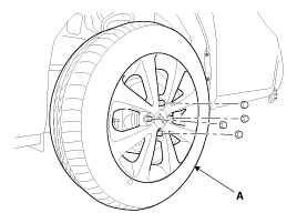
Remove the front wheel and tire (A) from front hub .
|

| 3. |
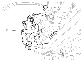
Remove the brake caliper mounting bolts , and then hold the brake
caliper assembly (B) with wire.
|
| 4. |
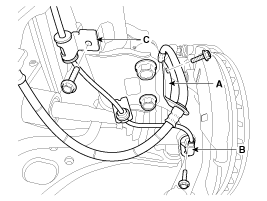
Remove the brake hose mounting bracket (A) & wheel speed sensor
(B) & bracket (C).
|
| 5. |
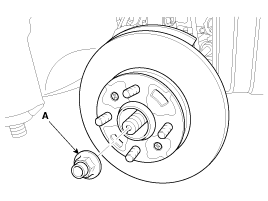
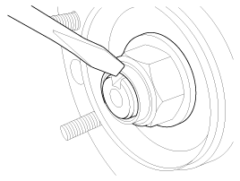
Remove driveshaft nut (A) from the front hub under applying the
brake.
|
| 6. |
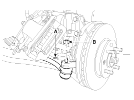
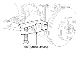
Remove the tie rod end ball joint from the knuckle.
|
| 7. |
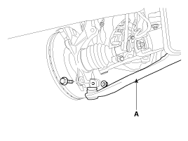
Remove the lower arm (A) from the knuckle.
|
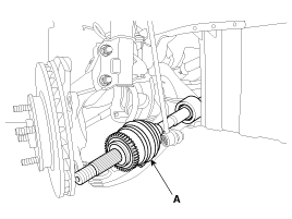
| 8. |
Disconnect the driveshaft (A) from the front hub assembly.
|
| 9. |
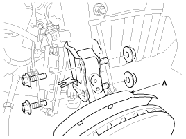
Loosen the strut mounting bolts and then remove the knuckle assembly
(A).
|
| 10. |
Install in the reverse order of removal.
|
 Front Hub / Knuckle Components
1. Snap ring
2. Bearing
3. Axle assembly
4. Brake disc dust cover
5. Wheel hub assembly
6. Wheel brake disc
7. Brake disc fixing screw
...
 Front Hub / Knuckle Disassembly
1.
Remove the snap ring (A).
2.
Remove the hub assembly from the knuckle assembly.
(1)
Install the ...
See also:
Removal
In case of removing the high pressure fuel pump, high pressure
fuel pipe, delivery pipe, and injector, there may be inju ...
Description
Ignition timing is controlled by the electronic control ignition timing
system.
The standard reference ignition timing data for the engine operating conditions
are pre-pro grammed in the ...
Servicing The Electrical System
1.
Prior to servicing the electrical system, be sure to turn off
the ignition switch and disconnect the battery ground cable.
&nb ...
Categories
- Kia Rio Manuals Home
- Kia Rio YB 2017-2026 Owners Manual
- Kia Rio YB 2017-2026 Service Manual
- Kia Rio UB 2012-2017 Owners Manual
- Kia Rio UB 2012-2017 Service Manual
- Downloads

Copyright © www.kirmanual.com 2014-2026