 Kia Rio: Head Lamps Adjustment
| Head Lamp Aiming Instructions |
The head lamps should be aimed with the proper beam-setting equipment,
and in accordance with the equipment manufacturer's instructions.
If there are any regulations pertinent to the aiming of head lamps
in the area where the vehicle is to be used, adjust so as to meet those
requirements.
|
Alternately turn the adjusting gear to adjust the head lamp aiming. If
beam-setting equipment is not available, proceed as follows:
| 1. |
Inflate the tires to the specified pressure and remove any loads
from the vehicle except the driver, spare tire, and tools.
|
| 2. |
The vehicle should be placed on a flat floor.
|
| 3. |
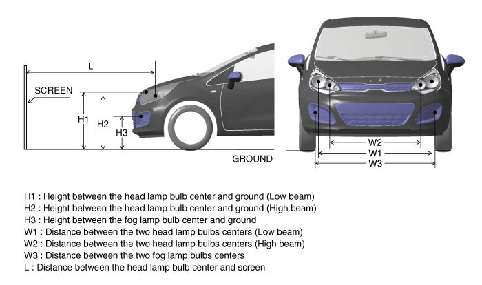
Draw vertical lines (Vertical lines passing through respective
head lamp centers) and a horizontal line (Horizontal line passing through
center of head lamps) on the screen.
|
| 4. |
With the head lamp and battery in normal condition, aim the head
lamps so the brightest portion falls on the horizontal and vertical
lines.
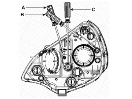
A : Vertical
B : Horizontal
C : Vertical (HLLD type)
|
Front Fog Lamp Aiming
The front fog lamps should be aimed as the same manner of the head lamps
aiming.
With the front fog lamps and battery normal condition, aim the front fog
lamps by turning the adjusting screw (A) with a driver.

Head Lamp And Fog Lamp Aiming Point


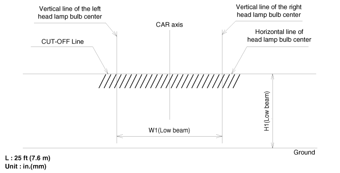
| 1. |
Head Lamp (Low beam)
|
| 2. |
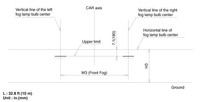
Turn the front fog lamp on without the driver aboard.
The cut-off line should be projected in the allowable range (shaded
region)
|
 Head Lamps Installation
1.
Install the head lamp assembly after connecting the connector.
2.
Install the radiator grille upper cover.
3.
...
 Turn Signal Lamp (Door mirror) Removal
Door Mirror Turn Signal Lamp
1.
Using a screwdriver or remover, remove the mirror (A) from th
mirror holder.
Becareful not to damage to the clip.
...
See also:
Thermostat: Removal
Disassembly of the thermostat would have an adverse effect, causing
a lowering of cooling efficiency.
...
Winter driving
Severe weather conditions in the winter result in greater wear and other problems.
To minimize the problems of winter driving, you should follow these suggestions:
Snowy or Icy conditions
To dri ...
BJ Boot Replacement
1.
Remove the front driveshaft. (Refer to DS group - ŌĆ£Front DriveshaftŌĆØ)
2.
Remove the TJ joint assembly. (Refer to DS group - ŌĆ£TJ JointŌĆ ...
Copyright ® www.kirmanual.com 2014-2026


