 Kia Rio: Operation

| 1. |
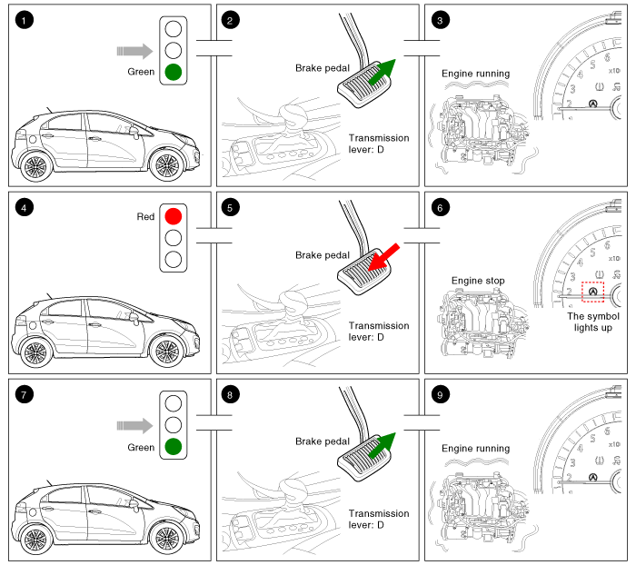
Vehicle moving.
|
| 2. |
The transmission lever position is D-range. The brake pedal is
released.
|
| 3. |
The engine is running. (Vehicle moving).
|
| 4. |
The driver brakes until the vehicle comes to a standstill.
|
| 5. |
The transmission lever position is D-range. The brake pedal is
pressed
|
| 6. |
The engine stops. The symbol "AUTO STOP" lights up in the instrument
cluster.
|
| 7. |
The driver wants to continue the journey.
|
| 8. |
The transmission lever position is D-range. The brake pedal is
released.
|
| 9. |
The engine is running again. The symbol goes out.
|
 Description
Idle Stop & Go (ISG) function automatically switches off the engine when
the car is at a standstill if the and starts it again as soon as the brake pedal
is released. This not only reduce ...
 Operation Condition for the ISG function
1. Auto stop or Auto start condition
(If all of the below condition are satisfied)
Items
State
Remark
Driving conditions
ISG OFF Switch
...
See also:
Door Switch Inspection
1.
Remove the door switch and check for continuity between the terminals.
...
Transaxle Control Module (TCM) Terminal Function
Connector [EGGG-AA]
Pin
Description
Pin
Description
22
Shift solenoid D (VFS-OD)
73
Inhibitor switch signal "S4"
...
Vehicle weight
This section will guide you in the proper loading of your vehicle and/or trailer,
to keep your loaded vehicle weight within its design rating capability, with or
without a trailer.
Properly loadi ...
Copyright ® www.kirmanual.com 2014-2026
